

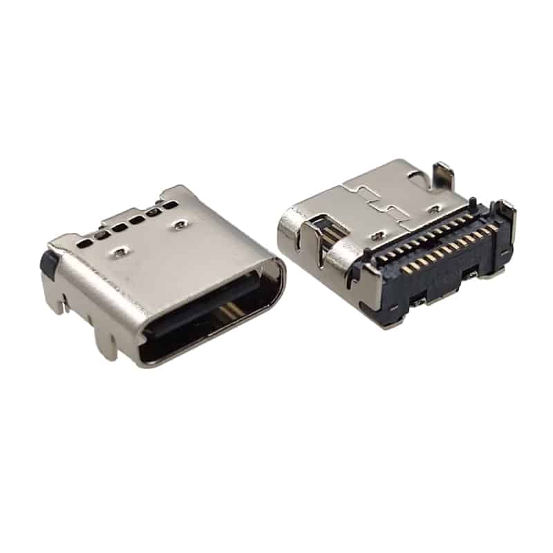
Mid mount usb c receptacle pinout type-c 24 Pin connector SMT CL=0.5MM l=8.21mm
USB C Receptacle Pinout 24 Pin SMT Mid-Mount Overview
The USB C receptacle pinout 24 pin SMT mid-mount is a full-featured USB Type-C female connector engineered for ultra-thin electronic devices requiring reduced board height. This 24 pin USB-C female connector features a mid-mount (sinking) SMT design with CL=0.5mm centerline height and 8.21mm body length, allowing the connector body to recess partially below the PCB surface. Fully compliant with USB-IF specifications, this SMT mid-mount USB-C solution supports USB4 Gen 3 data rates up to 40 Gbps and USB Power Delivery up to 5A/240W.
Engineered with a robust stainless steel shell and dual-row 24-pin SMT termination, this USB4 Type-C receptacle provides complete USB-C functionality including four SuperSpeed TX/RX differential pairs (Pins A2-A3, A10-A11, B2-B3, B10-B11), USB 2.0 D+/D- (Pins A6-A7, B6-B7), CC configuration channels (Pins A5, B5), VBUS power (Pins A4-A9, B4-B9), and SBU sideband signals (Pins A8, B8). The USB4 pinout configuration repurposes the SuperSpeed lanes for 4×12 Gbps FRL channels, delivering 40 Gbps total bandwidth. Manufactured under ISO 9001:2015 standards, this sinking USB-C connector is ideal for next-generation laptops, tablets, and 2-in-1 devices where every fraction of a millimeter counts.
The CL=0.5mm USB-C mid-mount design reduces the connector height above the PCB to just 0.5mm at the centerline, compared to 1.57mm for standard top-mount receptacles. This makes it possible to achieve sub-8mm total device thickness while maintaining full USB4 compatibility. Fully RoHS 3 and REACH compliant, this RoHS USB-C connector uses lead-free plating and high-temperature LCP housing (UL94V-0) rated for 260°C reflow soldering. Vistar Electronics offers free engineering samples and OEM/ODM customization for your ultra-slim device requirements.
24 Pin USB-C Female Connector SMT Mid-Mount Specifications
| Parameter | Specification |
|---|---|
| Part Number | USB-TC24-F24 |
| Type | USB Type-C Female Receptacle, 24-Pin, SMT Mid-Mount |
| Pin Count | 24 Pins (Full-Featured, Double Row) |
| Mounting Style | SMT Mid-Mount (Sinking / Recessed) |
| Centerline Height (CL) | 0.5mm |
| Body Length | 8.21mm |
| Shell Type | Stainless Steel with Dual Side Retention Tabs |
| Current Rating | 5A Max (VBUS pins), 1.25A (VCONN) |
| Voltage Rating | 30V DC Max (USB PD 3.1 EPR: 48V) |
| Insertion Force | 5–20N |
| Withdrawal Force | 8–20N |
| Operating Life | 10,000 Mating Cycles |
| Contact Material | Copper Alloy, Gold Plated (Contact Area) |
| Contact Resistance | ≤40 mΩ |
| Insulation Resistance | ≥100 MΩ |
| Withstanding Voltage | AC 100V (1 min) |
| Operating Temperature | -40°C to +85°C |
| Shell Material | Stainless Steel, Nickel Plated |
| Housing Material | LCP (Liquid Crystal Polymer), UL94V-0 |
| Compliance | USB 2.0/3.2/USB4, USB PD 3.1, RoHS 3, REACH |
| Data Rate Support | Up to 40 Gbps (USB4 Gen 3) |
| Power Delivery | Up to 240W (48V/5A via USB PD 3.1 EPR) |
| PCB Retention | 4 Solder Tabs + 2 Shell Brackets |
| Packaging | Tape & Reel |
| Certification | ISO 9001:2015 |
Related Part Numbers
- USB-TC24-F24 – 24-pin USB-C female, SMT mid-mount, CL=0.5mm, L=8.21mm
- USB-TC24-F25 – 24-pin USB-C female, SMT mid-mount, CL=0.47mm, L=8.7mm
- USB-TC24-F10 – 24-pin USB-C female, SMT top-mount, CL=1.57mm, L=9.17mm
- USB-TC24-F12 – 24-pin USB-C female, SMT right-angle, CL=1.32mm, L=8.21mm
- USB-TC24-F18 – 24-pin USB-C female, SMT vertical, straight, full height
- USB-TC16-F09 – 16-pin USB-C female, DIP vertical, H=6.5mm
- USB-TC6-F02 – 6-pin USB-C female, SMT mid-mount, charging-only
Key Features of USB4 Type-C Receptacle SMT Mid-Mount
⚡ 40Gbps USB4 Gen 3
Full 24-pin configuration supports USB4 Gen 3 up to 40 Gbps via 4×12 Gbps FRL lanes, compatible with Thunderbolt 3/4 and USB 3.2 Gen 2×2.
📏 Ultra-Low CL=0.5mm Profile
Sinking USB-C connector design with 0.5mm centerline height enables sub-8mm total device thickness for ultra-slim laptops and tablets.
🔋 240W USB PD Ready
Supports USB PD 3.1 EPR up to 48V/5A (240W), enabling fast charging for high-performance laptops and power stations.
🔒 Robust Mid-Mount Retention
Dual stainless steel shell brackets plus four SMT solder tabs provide superior mechanical retention for frequently used ports.
🛡️ Full EMI Shielding
Complete stainless steel shell with nickel plating ensures excellent EMI/RFI protection for high-speed signal integrity.
🌡️ High-Temp Reflow Compatible
LCP housing rated for 260°C peak reflow temperature, compatible with lead-free RoHS soldering processes.
♻️ RoHS & REACH Compliant
Lead-free plating and halogen-free materials meet EU and global environmental export standards.
🎬 Alt Mode Video Support
SBU pins enable DisplayPort and HDMI Alt Mode, delivering 8K video through a single connector.
Applications of SMT Mid-Mount USB-C Connector
Ultrabooks, Chromebooks, MacBook-style designs requiring sub-8mm thickness
iPad Pro competitors, Surface-style hybrids, Android tablets with keyboard docks
USB-C hubs, Thunderbolt docks, multi-port expansion stations for workspace setups
Steam Deck, ASUS ROG Ally, Nintendo Switch successors, portable consoles
Ruggedized tablets, HMI panels, field service devices requiring slim profiles
In-car tablets, rear-seat entertainment, center console displays with USB-C charging
Portable ultrasound, patient monitors, diagnostic tablets requiring slim waterproof designs
Smart displays, kiosk terminals, digital signage controllers with space constraints
FAQ
What is a USB-C receptacle pinout 24 pin SMT mid-mount?
What is the difference between mid-mount and top-mount USB-C receptacles?
What is the USB-C 24-pin pinout and signal assignment?
Does this connector support USB4 and Thunderbolt?
What does CL=0.5mm mean for USB-C mid-mount connectors?
Are your USB-C connectors RoHS and REACH compliant?
What is the MOQ and lead time?
Do you provide PCB layout guidelines for mid-mount USB-C?

USB C Connector female 24 pin top mount right angle
USB-C Connectors 24Pin SMT for High-Speed Data & Power Applications
24 Pin USB-C Connector Female SMT | USB 4.0 Type-C Receptacle | Vistar Electronics

USB-C Connector waterproof 6pin SMT vertical

USB Type-C Receptacle 24P Vertical SMD T/H Connector for High-Speed USB 3.1 Applications

Top mount USB Type C Receptacle 24pin Double shells USB 4.0 pcb connector SMT cL=1.32mm l=8.21mm

USB4 Female Type c USB connector 24 Pin mid-mount SMT CL=0.5mm L=8.17mm

Surface mount USB C connector smt 24pin right angle CL=1.57mm L=9.17

USB-C Connector Types Explained: A Complete Guide for Engineers and Buyers
If you’re a hardware engineer or sourcing professional selecting USB-C connectors for your next PCB design, understanding the different USB-C connector types...

Waterproof USB-C Connector Guide: IP67, IP68 & Design for Harsh Environments
Explore waterproof USB-C connector guide—IP67 vs IP68 ratings, sealing mechanisms, key specifications, and selection criteria for automotive, marine, and industrial applications. You...
USB-C Connector Ultimate Guide
You are designing the next generation of a portable medical device. The product requires high-speed data transfer, 100W power delivery for fast...