
Learn how to select the right USB-C mid mount connector for ultra-thin devices. Compare mounting styles, PCB layout requirements, power delivery, and common design mistakes to avoid.
You are designing a next-generation ultra-thin laptop. The mechanical team has handed you a Z-height budget that leaves exactly 3.2 mm for the USB-C port — including the connector, the PCB, and the enclosure wall. A standard top-mount USB-C receptacle alone consumes nearly that entire budget. What do you do?
This is the reality hardware engineers face daily. The demand for thinner, lighter devices has pushed conventional USB-C mounting styles to their limits. And this is precisely why the USB-C mid mount connector has become one of the most critical components in modern electronics design.
Unlike traditional connectors that sit entirely above the PCB surface, a mid-mount (also called sinking or recessed) USB-C receptacle drops into a precision-routed slot in the PCB. The connector body sits partially below the board surface, dramatically reducing the total height above the PCB. Some designs achieve centerline heights as low as 0.3 mm to 0.5 mm, enabling sub-8 mm total device thickness.
But here is the catch: mid-mount connectors are also the most challenging USB-C variants to design and lay out correctly. The PCB requires a routed cutout. The footprint spans both top and bottom layers. High-speed signals must navigate around the slot. And a single mistake in the PCB layout can render the entire board unmanufacturable.
This guide walks you through everything you need to know — from the fundamental differences between mounting styles to the eight critical design factors, PCB layout recommendations, common mistakes to avoid, and a practical selection framework. Whether you are an engineer, a hardware designer, or a procurement professional evaluating mid mount USB-C connector options for your next project, this is your technical reference.
What Is a USB-C Mid Mount Connector?
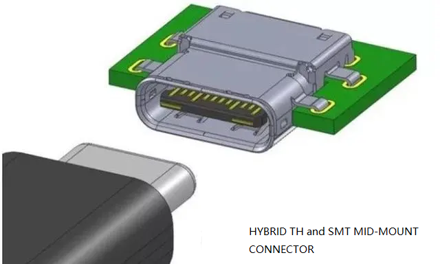
A USB-C mid-mount connector is a receptacle that mounts into a routed cutout at the edge of the PCB. Unlike conventional surface-mount connectors that sit entirely on top of the board, the mid-mount design shifts the component to the PCB edge, with component pads located on both the underside and the topside of the board.
Think of it this way: a top-mount connector sits on the board; a mid-mount connector sits in the board.
This recessed mounting style allows the connector’s mating interface to sit nearly flush with the device enclosure. The connector tongue centers within the PCB cutout, enabling overall heights that top-mount designs simply cannot match.
Mid-mount connectors are available in various pin counts — 6-pin for charging-only applications, 9-pin and 16-pin for USB 2.0, and 24-pin for full-featured USB 3.1 Gen 2 and USB4 support. Some variants also offer waterproof IP67 ratings for industrial and outdoor applications.
The trade-off is clear: mid-mount requires PCB milling, a more complex footprint, and more careful design. But it delivers the lowest possible profile — often the difference between a 10 mm tablet and an 8 mm tablet.
Mid-Mount vs. Top-Mount vs. Bottom-Mount: A Technical Comparison
Understanding the differences between mounting styles is essential before committing to a design direction.
| Feature | Mid-Mount | Top-Mount | Bottom-Mount |
|---|---|---|---|
| Overall Height Above PCB | Lowest (as low as 0.5 mm CL) | Standard (1.57 mm+ CL) | Standard |
| PCB Milling Required | Yes | No | No |
| Footprint Complexity | High (dual-layer SMT) | Low (single-layer SMT) | Medium |
| PCB Thickness Flexibility | High | Limited | Limited |
| Best For | Ultra-thin devices | Standard devices | Space-constrained underside |
Mid-Mount requires a routed hole in the PCB, with the connector dropping into the board and soldered in place. The connector’s component pads are located both on the underside and the topside of the PCB. This is the only choice for super low-profile applications.
Top-Mount is the traditional approach — the connector sits entirely on top of the PCB surface. Simple to design and assemble, but adds the full connector height to the device thickness.
Bottom-Mount mounts the connector on the underside of the PCB. This can save top-side space but may complicate enclosure design and thermal management. Some manufacturers offer mid-mount variants in both top-insertion and bottom-insertion configurations.
The key takeaway: if your Z-height budget is tight, mid-mount is not optional — it is mandatory. But if you have the vertical space, top-mount will save you the headache of PCB routing and slot fabrication.
8 Critical Factors to Consider Before Selecting a Mid-Mount USB-C Connector
1. Overall Connector Height and Centerline
This is the number one reason engineers choose mid-mount. But “height” means different things:
- Centerline height (CL): The distance from the PCB surface to the connector centerline. Some mid-mount connectors achieve CL as low as 0.3 mm or 0.5 mm. JAE offers mid-mount receptacles with center height as low as -0.1 mm.
- Overall height above PCB: The total protrusion above the board surface. The USB-TC24-F24 from Vistar Electronics, for example, achieves a 0.5 mm centerline height with an 8.21 mm body length.
Design tip: Match the connector height to your device’s target thickness, accounting for enclosure walls, shielding, and PCB thickness. Do not just look at the connector datasheet — model the entire stack-up.
2. PCB Thickness Compatibility
Mid-mount connectors are designed for specific PCB thicknesses. Using the wrong thickness can cause misalignment between the connector and the board edge.
Würth Elektronik’s mid-mount receptacles, for example, specify PCB thicknesses of 1.00 mm or 1.60 mm. GCT offers horizontal mid-mount options with shell stake lengths for 0.60 mm, 0.95 mm, 1.20 mm, and 1.60 mm PCB thicknesses.
Design tip: Always verify the recommended PCB thickness in the connector datasheet before finalizing your board stack-up. If your PCB thickness falls outside the specified range, the connector may not seat correctly or solder properly.
3. PCB Slot Design and Fabrication
The PCB slot (cutout) is the most critical mechanical feature for mid-mount connectors. Get this wrong, and the connector won’t seat properly — or worse, won’t solder correctly.
Key considerations:
- Slot dimensions must match the connector body exactly. The smallest PCB milling tool diameter is typically 0.7 mm, so inside corners will have a radius.
- Copper-to-edge clearance — some mid-mount footprints specify 0 mm copper-to-edge clearance, which may violate standard PCB design rules. This requires working closely with your PCB manufacturer.
- No circuitry underneath — the slot removes that section of the board entirely.
Design tip: Work with your PCB manufacturer early to verify they can achieve the required slot tolerances. For 0.3 mm copper-to-edge clearance requirements, you may need to ignore the rule (with caution) or adjust the footprint.
4. Current Rating and Power Delivery
USB-C supports up to 240 W (48 V, 5 A) with USB PD 3.1. But not all mid-mount connectors are created equal.
- 6-pin mid-mount connectors typically support 3 A to 5 A for charging-only applications
- 16-pin and 24-pin connectors often support 5 A
- Some 24-pin mid-mount connectors support USB PD up to 240 W (48 V @ 5 A)
- Same Sky offers mid-mount connectors with 3 A to 5 A current ratings
Routing 5 A to a mid-mount connector is a PCB design challenge. About 125 mils of copper width is needed for 0.5 oz copper to safely carry 5 A.
Design tip: Match the current rating to your power delivery requirements. If you need 240 W charging, ensure your connector is rated for 5 A at 48 V — and plan your PCB power routing accordingly. Use inner-layer copper planes for high-current paths.
5. USB Standard Support
Mid-mount USB-C connectors come in various pin counts that determine which USB standards they support:
| Pin Count | USB Standard | Data Rate | Alt Mode |
|---|---|---|---|
| 24-Pin | USB4 / USB 3.1 Gen 2 | Up to 40 Gbps | DP / HDMI |
| 16-Pin | USB 2.0 | 480 Mbps | Not supported |
| 9-Pin | USB 2.0 | 480 Mbps | Not supported |
| 6-Pin | USB 2.0 (charging only) | 480 Mbps | Not supported |
Some 24-pin mid-mount connectors support USB 3.1 Gen 2 at 10 Gbps, while others support USB4 Gen 3 at 40 Gbps. Same Sky’s UJ40 series supports USB4 at 40 Gbps.
Design tip: Do not over-specify. If your device only needs charging (no data), a 6-pin mid-mount connector saves cost and simplifies routing. For full-featured devices requiring video output or Thunderbolt compatibility, 24-pin is non-negotiable.
6. Shell Design and EMI Shielding
The connector shell serves multiple purposes: mechanical retention, EMI shielding, and grounding. Mid-mount connectors with EMI ground shielding are the most challenging to lay out.
Key features to look for:
- Through-hole shell stakes — provide superior PCB retention
- Stainless steel shells — ensure stable electrical performance and durability
- Mid-plate reinforcement — the stainless steel mid-plate reinforces the receptacle tongue for long-term durability
Design tip: Some mid-mount connectors use 4 through-hole shell stakes for excellent PCB retention. Plan your PCB to accommodate these. Stack ESD protection devices on both top and bottom layers to get them as close to the connector as possible.
7. Housing Material and Thermal Performance
Liquid Crystal Polymer (LCP) is the standard housing material for high-reliability USB-C connectors. LCP offers:
- High temperature resistance (essential for reflow soldering)
- Low moisture absorption
- Dimensional stability
- UL94 V-0 flammability rating
Design tip: Verify the connector’s reflow soldering temperature rating matches your assembly process. Most mid-mount connectors are rated for 260°C maximum soldering temperature.
8. SMT Production and Assembly Compatibility
Mid-mount connectors present unique assembly challenges:
- Dual-row SMT — pads on both top and bottom of the board
- Hybrid SMT/THR — some use surface-mount contacts plus through-hole reflow stakes
- Pin-in-paste (PIP) compatibility — simplifies the production process
Design tip: Ensure your assembly partner has experience with mid-mount connectors. The stencil design is critical — paste volume must be carefully calculated for the dual-sided pads.
PCB Layout Recommendations for Mid-Mount USB-C Connectors
PCB layout is where mid-mount connectors separate experienced engineers from the rest. Here is a practical step-by-step approach based on real-world reference designs.
Step 1: Verify the Footprint — Twice
Get the latest footprint symbol from your connector vendor and double-check it. Work with your board manufacturing partner to verify the footprint and planarity of the connector. A test-build can save money down the road to work out any issues.
Common mistake: Trying to mount a mid-mount connector on top of the PCB like a standard SMD connector without the required PCB cutout.
Step 2: Via Placement
Use through-hole 8/16 mil vias (no blind or buried vias). Set differential net spacing to 3 mil (worst case) and tent vias on top and bottom. Make sure via holes do not hit the pads on the Type-C connector to avoid “via on pad”.
Step 3: Route High-Speed Differential Pairs First
Get the SuperSpeed TX/RX pairs out on the top and bottom layers first. These are the most critical signals — route them cleanly to reduce the number of serpentine bends needed for length matching. Refer to your board’s design rules for proper differential impedance.
Step 4: Route SBU, USB2, and CC Pins
Next, route the SBU, USB2 (D+/D-), and CC1/CC2 pins. The USB2 pins are often shorted on the connector itself — check your connector datasheet.
Step 5: Design the Power Delivery Path
Getting 5 A to a mid-mount connector is challenging, especially when copper is scarce near the connector.
Two effective methods:
- Inner-layer copper plane — use a sizable plane on an inner layer to carry high current. About 125 mils of copper width is needed for 0.5 oz copper to safely carry 5 A.
- Top/bottom layer pours — use top and bottom layers to carry the bulk of the current (place traces/pours away from the data path). About 65 mils with 0.5 oz copper (plus plating) will easily carry 5 A.
Once power is close to the connector, dedicate two pours on an inner layer to hit the VBUS vias under the connector and use a bank of vias to stitch them to the top/bottom pours.
Step 6: Ground Pour and Stitching
Pour ground on the top layer with a few additional vias. Expand the pour to connect the stabilizing through-holes on the front of the connector.
Typical Applications for Mid-Mount USB-C Connectors
Mid-mount USB-C connectors are found in virtually every product category where Z-height is constrained:
- Ultra-thin laptops and notebooks — the primary driver for mid-mount adoption
- Tablets and 2-in-1 devices — where every millimeter of thickness matters
- Docking stations — compact form factors with full-featured USB-C ports
- Mini PCs and embedded systems — space-constrained industrial computing
- Wearables and IoT sensors — smart rings, smart glasses, fitness trackers
- Portable medical devices — handheld diagnostic tools requiring slim profiles
- POS terminals and handheld scanners — commercial devices with limited internal volume
- Gaming handhelds and portable SSDs — consumer electronics pushing the limits of miniaturization
Common Design Mistakes and How to Avoid Them
Mistake 1: PCB Slot Dimensions Too Small
The connector won’t seat properly. The slot must match the connector body exactly, accounting for milling tool radius.
Solution: Provide the connector’s mechanical drawing to your PCB manufacturer before finalizing the board outline.
Mistake 2: Wrong PCB Thickness
Using a PCB thickness outside the connector’s specified range causes misalignment between the connector and the board edge.
Solution: Always verify the recommended PCB thickness in the connector datasheet.
Mistake 3: Incorrect Footprint
Using the wrong footprint or placing vias on pads causes assembly failures.
Solution: Get the latest footprint from your connector vendor. Double-check it. Then check it again.
Mistake 4: Shell Floating (Poor Grounding)
Inadequate shell grounding compromises EMI shielding and signal integrity.
Solution: Pour ground on the top layer and connect the stabilizing through-holes. Stack ESD protection devices close to the connector.
Mistake 5: Insufficient Current-Carrying Capacity
Routing 5 A through narrow traces causes voltage drop and overheating.
Solution: Use inner-layer copper planes or wide top/bottom pours for VBUS.
Mistake 6: Weak Mechanical Retention
Insufficient shell stakes or poor PCB anchoring lead to connector failure under repeated mating cycles.
Solution: Choose connectors with through-hole shell stakes and ensure proper PCB anchoring.
How to Choose the Right Mid-Mount Connector: A Decision Framework
Follow this decision flow to select the correct mid-mount USB-C connector for your application:
Need data transfer?
    ↓
    YES → Need USB4 / 40 Gbps?
    │         ↓
    │         YES → 24-Pin Mid-Mount [USB4 compatible]
    │         NO  → Need USB 3.1 Gen 2 / 10 Gbps?
    │               ↓
    │               YES → 24-Pin Mid-Mount
    │               NO  → 9-Pin or 16-Pin Mid-Mount (USB 2.0)
    │
    NO → Charging only?
          ↓
          YES → 6-Pin Mid-Mount (power-only)
          NO  → Re-evaluate requirements
Additional filters:
- Need waterproofing? → Choose IP67-rated mid-mount variants
- Need 240 W charging? → Ensure 5 A @ 48 V rating
- Need automated SMT assembly? → Verify reflow solder compatibility and PIP support
- Need customization? → Work with suppliers offering OEM/ODM options
Engineering Checklist for Mid-Mount USB-C Integration
Before finalizing your design, run through this checklist:
- [ ] PCB thickness matches connector specification
- [ ] PCB slot dimensions verified with manufacturer
- [ ] Copper-to-edge clearance confirmed (0 mm may require special handling)
- [ ] Footprint matches latest vendor drawing
- [ ] Vias placed away from pads (no via-on-pad)
- [ ] High-speed differential pairs routed on outer layers
- [ ] Differential impedance matched to board design rules
- [ ] VBUS current-carrying capacity verified (5 A capability)
- [ ] Ground pour connects all shell stakes
- [ ] ESD protection devices placed close to connector
- [ ] Reflow soldering temperature profile compatible with LCP housing
- [ ] Stencil design verified for dual-sided SMT pads
Final Thoughts
The USB-C mid mount connector is an engineering solution born from a fundamental physical constraint: devices are getting thinner, and connectors must follow. But selecting and implementing a mid-mount connector is not simply a matter of picking the lowest profile part from a catalog. It requires careful consideration of PCB thickness, slot fabrication, high-speed routing, power delivery, and assembly compatibility.
The connectors that succeed in production are those designed with the entire system in mind — not just the connector itself, but the PCB, the enclosure, and the manufacturing process.
For engineers and procurement professionals evaluating mid-mount USB-C options, working with a supplier that understands these system-level trade-offs makes the difference between a smooth development cycle and a costly respin. Vistar Electronics offers a comprehensive range of mid-mount USB-C connectors — from 6-pin charging-only variants to full-featured 24-pin USB4-compatible receptacles — with free engineering samples available for qualified projects. Their portfolio includes ultra-low profile designs with centerline heights as low as 0.5 mm, waterproof IP67 options, and RoHS/REACH-compliant components ready for high-volume SMT assembly.
Whether you are designing the next generation of ultra-thin laptops, industrial handhelds, or wearable devices, the right mid-mount connector is the difference between a product that meets its thickness target and one that does not. Choose wisely, lay out carefully, and always verify the footprint.
For additional engineering resources, explore the USB Type-C 24 Pin Connector Guide and the USB-C Connector Selection Guide. Official USB Type-C standards and compliance specifications are available from the USB Implementers Forum (USB-IF) and IEC International Standards.


