

USB-C Receptacle Pinout – 24-Pin SMT Mid-Mount Connector
24-pin USB-C SMT mid-mount receptacle — Product Overview (USB Type-C Receptacle Pinout for High-Speed Applications)
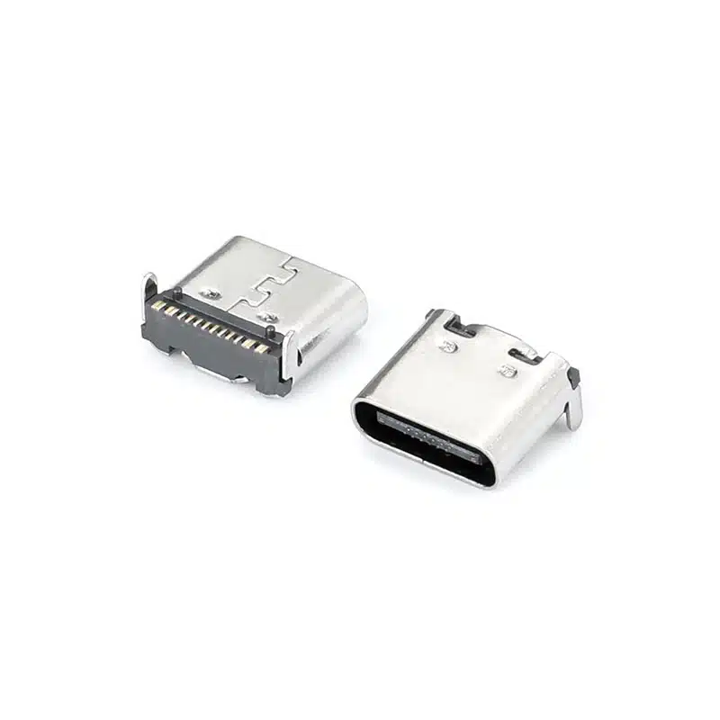
The USB-C receptacle pinout for the USB-TC24-F24 is a full-featured USB Type-C female connector engineered for ultra-thin electronic devices requiring reduced board height. As a USB Type-C receptacle pinout, it delivers complete USB-C functionality including four SuperSpeed TX/RX differential pairs, USB 2.0 D+/D-, CC configuration channels, VBUS power, and SBU sideband signals.
This 24 pin USB-C receptacle features a mid-mount (sinking) SMT design with CL=0.5mm centerline height and 8.21mm body length, allowing the connector body to recess partially below the PCB surface. The USB-C mid mount connector design reduces the connector height above the PCB to just 0.5mm at the centerline, compared to 1.57mm for standard top-mount receptacles.

Manufactured under ISO 9001:2015 standards, this connector uses high-temperature LCP housing (UL94V-0) rated for 260°C reflow soldering and is fully compliant with RoHS 3 and REACH directives. Vistar Electronics offers free engineering samples and OEM/ODM customization for your ultra-slim device requirements.
For designs requiring stronger mechanical PCB retention over pure SMT mounting, see our 24-pin USB-C DIP+SMT hybrid mount receptacle.
24 Pin USB-C Receptacle — Full Technical Specifications
| Parameter | Specification | Notes |
|---|---|---|
| Part Number | USB-TC24-F24 | Standard catalog item |
| Connector Type | USB Type-C Female Receptacle | 24-pin full-featured |
| Mounting Type | SMT Mid-Mount (Sinking) | CL=0.5mm |
| Pin Count | 24 Pins | Full USB-C functionality |
| Body Length | 8.21 mm | — |
| Centerline Height | 0.5 mm | Ultra-low profile |
| USB Standard | USB4 Gen 3 | Up to 40 Gbps |
| Power Delivery | USB PD 3.1 | Up to 240W (5A) |
| Current Rating | 5A max | — |
| Voltage Rating | 20V DC | — |
| Contact Material | Phosphor Bronze | Gold plated |
| Shell Material | Stainless Steel | EMI shielding |
| Insulator Material | LCP, UL94V-0 | High-temperature, 260°C reflow |
| Operating Temperature | −25 °C to +85 °C | — |
| Mating Cycles | 10,000 cycles | Durability |
| Compliance | RoHS 3, REACH, USB-IF | Global export ready |
| Packaging | Tape & Reel | SMT assembly ready |
Why Engineers Choose This USB-C Mid Mount Connector for Ultra-Thin Devices
CL=0.5mm Ultra-Low Profile — Enables Sub-8mm Device Thickness
The mid-mount (sinking) design reduces connector height above the PCB to just 0.5mm at the centerline, compared to 1.57mm for standard top-mount receptacles — making sub-8mm total device thickness achievable.
USB4 Gen 3 — 40 Gbps High-Speed Data
Supports USB4 Gen 3 with data rates up to 40 Gbps. The USB4 pinout repurposes the SuperSpeed lanes for 4×12 Gbps FRL channels, delivering 40 Gbps total bandwidth.
Full 24-Pin USB-C Functionality
Includes four SuperSpeed TX/RX differential pairs (Pins A2-A3, A10-A11, B2-B3, B10-B11), USB 2.0 D+/D- (Pins A6-A7, B6-B7), CC configuration channels, VBUS power, and SBU sideband signals.
RoHS 3 & REACH Compliant — Globally Export Ready
Fully compliant with RoHS 3 and REACH directives, using lead-free plating and high-temperature thermoplastic materials that meet global environmental standards.
Free Samples & OEM/ODM Customization
Vistar offers free engineering samples and OEM/ODM customization including custom plating, packaging, and mechanical modifications.
USB-C Pin Assignment — Complete 24-Pin USB Type-C Receptacle Pinout Table
The USB-C receptacle pinout (also called USB Type-C receptacle pinout) consists of 24 pins arranged in two rows of 12 (A and B sides). The following table provides the complete USB-C pin assignment for the 24-pin full-featured receptacle.
| Pin | Signal | Description | Pin | Signal | Description |
|---|---|---|---|---|---|
| A1 | GND | Ground | B12 | GND | Ground |
| A2 | TX1+ | SuperSpeed TX Pair 1, Positive | B11 | RX1+ | SuperSpeed RX Pair 1, Positive |
| A3 | TX1− | SuperSpeed TX Pair 1, Negative | B10 | RX1− | SuperSpeed RX Pair 1, Negative |
| A4 | VBUS | Bus Power | B9 | VBUS | Bus Power |
| A5 | CC1 | Configuration Channel 1 | B8 | SBU2 | Sideband Use 2 |
| A6 | D+ | USB 2.0 Data Positive | B7 | D− | USB 2.0 Data Negative |
| A7 | D− | USB 2.0 Data Negative | B6 | D+ | USB 2.0 Data Positive |
| A8 | SBU1 | Sideband Use 1 | B5 | CC2 | Configuration Channel 2 |
| A9 | VBUS | Bus Power | B4 | VBUS | Bus Power |
| A10 | RX2− | SuperSpeed RX Pair 2, Negative | B3 | TX2− | SuperSpeed TX Pair 2, Negative |
| A11 | RX2+ | SuperSpeed RX Pair 2, Positive | B2 | TX2+ | SuperSpeed TX Pair 2, Positive |
| A12 | GND | Ground | B1 | GND | Ground |
Pin assignments follow the USB Type-C Connector Specification, making the USB-TC24-F24 suitable for USB4, USB 3.2, and USB Power Delivery designs where the system architecture supports these standards.
For the official USB Type-C connector requirements and implementation details,
refer to the USB Type-C Cable and Connector Specification published by USB-IF.
USB-C Pin Functions Explained
VBUS and GND — The Power Backbone: USB-C carries four VBUS pins (A4, A9, B4, B9) and four GND pins (A1, A12, B1, B12). Running four power and four ground pins in parallel reduces contact resistance, minimizes voltage drop, and enables the 5A/240W power delivery capability of USB PD 3.1.
SuperSpeed Differential Pairs (TX/RX): The USB-C 24 pin pinout includes four SuperSpeed differential pairs: TX1+/− (A2/A3), RX1+/− (B11/B10), RX2+/− (A10/A11), and TX2+/− (B3/B2). These pairs support USB 3.2 Gen 2×2 (20 Gbps) and USB4 Gen 3 (40 Gbps) data rates.
Configuration Channel (CC1/CC2): Pins A5 (CC1) and B5 (CC2) detect plug orientation, establish power roles (source or sink), negotiate USB Power Delivery contracts, and enable Alternate Mode entry. Only one CC pin is active at a time — the other provides VCONN power for active cables.
USB 2.0 Data Lines (D+/D−) and Sideband Use (SBU1/SBU2): Pins A6/A7 and B6/B7 carry USB 2.0 data for backward compatibility. Pins A8 (SBU1) and B8 (SBU2) are used for Alternate Mode functions such as DisplayPort AUX or analog audio.
USB-C Receptacle Dimensions and Cutout
When designing a PCB for a 24-pin USB-C mid-mount receptacle, the USB-C receptacle dimensions and the corresponding PCB cutout are the two most critical mechanical parameters. They determine whether the connector sits flush with the board edge, whether the mating cable can be inserted without interference, and whether the finished assembly fits inside the product enclosure.
USB-C Port Opening Dimensions
The standard USB-C receptacle opening measures approximately 8.94 mm wide by 3.16 mm high, with a corner radius of roughly 1.3 mm[reference:0]. These values describe the external port opening — the visible cutout that the USB-C plug enters. Different manufacturers may apply minor tolerances, so the exact port opening should always be verified against the selected connector’s mechanical drawing rather than assumed from the standard alone.
For enclosure design, the port opening must be slightly larger than the connector’s mating face to allow unrestricted plug insertion. A clearance of 0.1–0.2 mm per side is typically sufficient for moulded plastic or machined metal panels. If the connector is recessed behind a panel, the depth of the recess also becomes part of the USB-C port dimensions calculation.
PCB Cutout for Mid-Mount Receptacles
A mid-mount USB-C receptacle is not soldered onto the top surface of the PCB. It drops into a routed cutout so that the connector body sits partially below the board surface. This is what enables the low-profile port position that mid-mount connectors are chosen for in ultra-thin devices.
The PCB cutout for a mid-mount receptacle is therefore larger than a simple port opening. It must accommodate the connector’s body width, depth, and mounting features. Common mid-mount cutout drawings specify routing along the PCB edge with specific corner radii to match the connector housing. The cutout dimensions vary between connector series, so the PCB cutout drawing supplied by the connector manufacturer is the only reliable reference. Do not derive a mid-mount cutout from a top-mount footprint or from the port opening dimensions alone.
PCB thickness is another variable. Mid-mount connectors are often specified for a particular board thickness range — commonly 0.6 mm, 0.8 mm, or 1.6 mm. Using a connector outside its specified board-thickness range can change the connector’s centreline height relative to the PCB surface, affecting both port alignment and solderability.
Connector Body Height and Mounting Datum
For mid-mount connectors, the centreline height (CL) — the distance from the PCB surface to the centre of the connector opening — is a key datum. A lower CL means the port sits closer to the board surface, which reduces the required enclosure height but also reduces the clearance between the connector body and the underside of the board. The mechanical drawing should specify both the CL and the overall body depth so that the PCB layout engineer can confirm there is no interference with components on the opposite side of the board.
If the connector is mounted near a PCB edge, the distance from the board edge to the connector body is also critical. This edge distance determines how much board material remains around the cutout and influences the mechanical rigidity of the assembly.
Engineering note: Always request the current product drawing before finalising the PCB cutout. The values above describe standard USB-C port opening dimensions; the mid-mount PCB cutout is specific to the connector series and must be taken from the manufacturer’s drawing.
24-Pin USB-C Receptacle Pinout for PCB Design
The 24-pin USB-C receptacle pinout is the complete signal map of the connector. For PCB designers, understanding this pinout is essential for routing the Main Link differential pairs, the USB 2.0 data lines, the Configuration Channel (CC) signals, and the VBUS power rails correctly.
Receptacle Pin Assignment (Front View)
| Pin | Signal | Pin | Signal |
|---|---|---|---|
| A1 | GND | B12 | GND |
| A2 | TX1+ | B11 | RX1+ |
| A3 | TX1− | B10 | RX1− |
| A4 | VBUS | B9 | VBUS |
| A5 | CC1 | B8 | SBU2 |
| A6 | D+ | B7 | D− |
| A7 | D− | B6 | D+ |
| A8 | SBU1 | B5 | CC2 |
| A9 | VBUS | B4 | VBUS |
| A10 | RX2− | B3 | TX2− |
| A11 | RX2+ | B2 | TX2+ |
| A12 | GND | B1 | GND |
The A and B rows are not simple mirror images. They are symmetric about the connector’s central origin. When a plug is inserted upright, A5 (CC1) connects to the cable’s CC line. When flipped, B5 (CC2) takes over. This origin-symmetric layout is what enables reversible insertion without mechanical switches inside the connector[reference:1].
Signal Groups for PCB Routing
VBUS and GND: Four VBUS pins (A4, A9, B4, B9) and four GND pins (A1, A12, B1, B12) run in parallel. This reduces contact resistance and enables high-current power delivery. On the PCB, VBUS and GND should be routed with adequate copper width for the rated current — typically 5A for a full-featured 24-pin receptacle.
SuperSpeed Differential Pairs: The 24-pin pinout provides four SuperSpeed differential pairs — TX1+/− (A2/A3), RX1+/− (B11/B10), RX2+/− (A10/A11), and TX2+/− (B3/B2). These pairs carry high-speed data for USB 3.2 Gen 2 (10 Gbps) and USB4 (up to 40 Gbps). On the PCB, they require controlled-impedance routing, matched trace lengths within each pair, and a continuous reference plane.
USB 2.0 Data: Pins A6/A7 and B6/B7 carry the USB 2.0 D+ and D− signals. Both pairs are typically connected to a single USB 2.0 transceiver on the PCB. These signals are less critical than the SuperSpeed pairs but should still be routed with reasonable care to avoid excessive stub lengths.
Configuration Channel (CC1/CC2): Pins A5 and B5 are the CC lines. They detect plug orientation, establish power roles, and negotiate USB Power Delivery contracts. The CC traces should be routed to the PD controller with appropriate pull-down resistors (for a sink) or pull-up resistors (for a source). Both CC1 and CC2 must be routed because the connector orientation is not known in advance.
Sideband Use (SBU1/SBU2): Pins A8 and B8 are the sideband pins. They are used for Alternate Mode functions such as DisplayPort AUX channel or analog audio. If Alt Mode is not used in the design, the SBU pins can be left unconnected or terminated according to the system requirements.
PCB Footprint Considerations
The pinout table above describes the electrical assignment. The physical PCB footprint — pad positions, pad sizes, and terminal spacing — must come from the connector manufacturer’s recommended land pattern. A mid-mount SMT connector may have two rows of SMT pads plus additional through-hole anchor pins for mechanical retention. The footprint drawing should be followed exactly; do not derive pad positions from the pinout table alone.
For a more detailed explanation of USB-C pin functions and the differences between 24-pin, 16-pin, and 6-pin configurations, see our USB-C Connector Pinout Guide.
USB-C Female Receptacle PCB Mounting Options
The USB-C female receptacle PCB mounting option determines how the connector is attached to the board, how much vertical space it consumes, and how much mechanical stress it can withstand. There is no single “best” mounting style — the right choice depends on the enclosure height, the expected number of mating cycles, and the assembly process.
SMT Top-Mount
The connector sits entirely on the top surface of the PCB. All signal and anchor pads are SMT-soldered to the top layer. This is the most straightforward mounting style for reflow assembly, but it also consumes the most vertical height above the board. It is suitable for products where enclosure height is not the primary constraint.
Mid-Mount (Sinking)
A mid-mount receptacle drops into a PCB cutout so that part of the connector body sits below the board surface. This reduces the height above the PCB, enabling thinner enclosures. The trade-off is a more complex PCB fabrication step (routing the cutout) and a footprint that is specific to the connector series. Mid-mount is commonly used in tablets, ultra-thin laptops, and compact consumer devices where every millimetre of vertical space matters.
Top-Mount vs Mid-Mount vs Bottom-Mount
USB-C receptacles can be mounted on the top of the PCB, recessed into a cutout (mid-mount), or mounted on the bottom side of the board. Bottom-mount connectors are less common for receptacles but can be useful when the port must face downward relative to the main component side. The GCT USB orientation guide describes these distinctions: a top mid-mount fits into a PCB hole and is soldered to the top side, while a bottom mid-mount is soldered from the opposite side[reference:2].
Through-Hole Anchor Pins
Many mid-mount and top-mount USB-C receptacles include through-hole anchor pins in addition to the SMT signal pads. These pins pass through the PCB and are wave-soldered or selective-soldered from the back side. They provide significantly stronger mechanical retention than SMT pads alone, which is important because a USB-C port experiences repeated insertion and extraction forces. The combination of SMT signal pads and through-hole anchors is sometimes called a hybrid mounting configuration.
Back-Mount and PCB Edge Mounting
Some USB-C receptacles are designed for board-edge or back-mount configurations, where the connector is positioned at the edge of the PCB rather than in the centre of the board. This can be useful when the port must align with a side panel or rear panel opening. The connector orientation — right-angle, vertical, or horizontal — determines which direction the cable enters relative to the PCB. For a mid-mount right-angle receptacle, the cable exits parallel to the board, which is the configuration used in most thin devices.
Choosing a Mounting Style
When selecting a mounting style, consider the following factors:
- Enclosure height: Mid-mount reduces height above the PCB; top-mount requires more vertical clearance.
- PCB thickness: Mid-mount connectors are often specified for a particular board thickness range.
- Mechanical stress: Through-hole anchors provide stronger retention than pure SMT.
- Assembly process: SMT-only connectors are reflow-compatible; hybrid connectors require an additional wave or selective solder step.
- Port orientation: Right-angle for side-exit cables; vertical for top-exit cables.
- Cutout complexity: Mid-mount requires a routed PCB cutout; top-mount does not.
The product on this page is a 24-pin mid-mount SMT receptacle with a right-angle configuration. Its mounting style reduces the height above the PCB and positions the port for side-entry cable access, which is the appropriate choice for compact, thin-profile electronic equipment.
USB-C PCB Footprint — Recommended Land Pattern and Layout Guidelines
The USB-C PCB footprint for this 24-pin SMT mid-mount receptacle requires careful attention to pad design, via placement, and PCB cutout dimensions. These PCB layout guidelines are based on USB-IF specifications and industry best practices.
Recommended Land Pattern
- Pad Size: Follow the manufacturer’s recommended land pattern exactly — do not guess dimensions
- Via Placement: Use through-hole 8/16 mil vias (no blind or buried vias) for reliable connections
- Trace Spacing: Set differential pair spacing to 3 mil minimum (worst case)
- Via Tenting: Tent vias on top and bottom to prevent solder wicking
PCB Cutout for Mid-Mount Design
For this USB-C mid mount connector (also called sinking or recessed), a cutout must be routed in the PCB outline. The connector drops into the PCB cutout and is soldered in place. No circuitry can be placed underneath the connector as this section of the board is removed. PCB thickness options of 0.6mm or 0.8mm are commonly used.
High-Speed Routing Guidelines
- Place the Type-C connector at the board edge — prioritize routing high-speed differential pairs first, then CC signals, then power and ground
- Minimum recommended space between copper elements: 8 mil (0.203 mm)
- Use dedicated planes for power and ground to reduce jitter on USB signals
- Keep trace length to 1.5 inches (25-30 mm) or less for optimal signal integrity
USB-C Receptacle Dimensions — Mechanical Drawing and Form Factor
The USB-C receptacle dimensions for this mid-mount connector are critical for PCB mechanical design and enclosure fit.
Key Dimensions
| Parameter | Value |
|---|---|
| Centerline Height (CL) | 0.5 mm |
| Body Length | 8.21 mm |
| PCB Cutout Depth | Refer to datasheet |
| Mounting Type | SMT Mid-Mount (Sinking) |
For complete mechanical drawings including PCB cutout dimensions, recommended land pattern, and 3D STEP models, refer to the USB Type-C Specification R2.0 or contact Vistar Electronics for manufacturer-specific documentation.
Where to Use This 24 Pin USB-C Receptacle — Applications Across Industries
As a versatile 24 pin USB-C receptacle, the USB-TC24-F24 is ideal for any application where board height is constrained but full USB4 functionality is required. The CL=0.5mm design enables total device thickness below 8mm while maintaining 40 Gbps data rates and 240W power delivery.
USB-C Receptacle Pinout — Frequently Asked Questions
What is a USB-C receptacle pinout?
A USB-C receptacle pinout is the assignment of signals to each of the 24 pins in a USB Type-C female connector. The pinout defines which pins carry power (VBUS), ground (GND), high-speed data (TX/RX), USB 2.0 D+/D−, configuration channels (CC1/CC2), and sideband signals (SBU1/SBU2). Understanding the USB Type-C receptacle pinout is essential for correct PCB design.
How many pins are in a USB-C receptacle?
A full-featured USB-C receptacle has 24 pins arranged in two rows of 12 (A side and B side). The 24 pin USB-C receptacle is required for USB4, SuperSpeed data, and Alternate Mode video output. Variants include 16-pin, 12-pin, and 6-pin charging-only configurations.
What is the function of CC1 and CC2 pins?
CC1 (A5) and CC2 (B5) are the Configuration Channel pins. They detect plug orientation, establish power source/sink roles, negotiate USB Power Delivery contracts, and activate Alternate Mode functions. When plug inserted normally, CC1 works; flipped plug switches to CC2 signal path.
What is a mid-mount USB-C connector?
A USB-C mid mount connector (sinking/recessed type) installs into a PCB cutout, part of the connector body sits under PCB surface. It only leaves 0.5mm height on PCB surface, versus 1.57mm of standard top-mount receptacle, perfect for ultra-slim hardware.
Does this connector support USB4?
Yes. This 24 pin USB-C receptacle fully supports USB4 Gen 3 up to 40 Gbps bandwidth, utilizing four groups of SuperSpeed differential lanes for FRL high-speed transmission.
Does it support USB Power Delivery?
Yes. This receptacle supports USB Power Delivery 3.1 up to 240W 5A power transmission. Four parallel VBUS and GND pins reduce contact resistance to realize high-current charging performance.
Can I get PCB footprint files?
Yes. Vistar Electronics provides 2D drawings, 3D STEP models, recommended PCB footprint layouts upon request. Contact our engineering team at sales@vistarelectronics.com for design files.
What is the difference between a receptacle and a plug?
A receptacle is female port soldered to PCB on devices. A plug is male cable end inserted into receptacle. Their pin wiring differs: cable plug only routes one CC line, the other pin becomes VCONN power for eMarker cables.
USB-C Receptacle Pinout Guide — Complete Reference for Engineers and PCB Designers
What Is a USB-C Receptacle Pinout?
A USB-C receptacle pinout is the complete mapping of electrical signals to the 24 pins of a USB Type-C female connector. This USB Type-C receptacle pinout defines every connection point including VBUS power, GND ground, SuperSpeed TX/RX high-speed lanes, USB2.0 D+/D-, CC configuration pins and SBU sideband pins. Mastering USB-C pin assignment is mandatory for hardware engineers and PCB layout designers developing consumer or industrial electronics.
The USB Type-C standard unifies legacy USB-A/B/Micro ports into one reversible connector, supporting 40Gbps USB4 data and up to 240W USB PD charging, plus video output via alternate mode protocols.
USB-C 24-Pin Pinout — Understanding the Signal Assignment
The USB-C 24 pin pinout splits contacts into two A/B rows each with 12 pins, which enables reversible plug insertion. When the cable is flipped, B-side pins take over all signal functions to keep data and power transmission stable.
Core pin function groups:
- VBUS (A4, A9, B4, B9): Power rail, compatible with USB PD 3.1 48V/5A power supply
- GND (A1, A12, B1, B12): Power return ground paths
- TX/RX Differential Pairs: Four groups of high-speed differential signals for USB4 40Gbps bandwidth
- D+/D−: Backward compatible USB 2.0 low-speed signal lines
- CC1/CC2: Detection & power negotiation control pins
- SBU1/SBU2: Auxiliary sideband for DP alt mode and analog audio
USB-C PCB Footprint and Layout Guidelines
Proper USB-C PCB footprint design ensures signal integrity and stable soldering yield for mid-mount Type-C connectors. Mid-mount variants require pre-routed PCB cutout where no circuit traces can be placed underneath the connector cavity; typical board thickness uses 0.6/0.8mm.
Layout best practices: strictly follow factory pad dimension specs, use 8/16mil through vias, separate high-speed differential traces with minimum 3mil gap, fully tent vias to avoid solder wicking. Place Type-C at PCB edge and route SuperSpeed lanes first for minimal signal loss.
USB-C Receptacle Dimensions and Mechanical Design
This USB-C mid mount connector features ultra-low 0.5mm centerline height and 8.21mm body length, allowing finished equipment total thickness under 8mm without sacrificing full USB4 & PD performance. Official mechanical drawings, PCB cutout templates and 3D STEP files are available via Vistar engineering support.
USB-C Mid-Mount Connector — Advantages for Ultra-Thin Devices
Compared to conventional top-mount Type-C sockets (1.57mm board height), mid-mount sinking design recesses connector into PCB cutout, drastically reducing the vertical space occupied inside slim laptops, tablets and portable monitors while retaining full 24-pin high-speed, high-power pin configuration.
USB-C Connector Pinout — 24-Pin vs 16-Pin vs 6-Pin
- 24-Pin Full Featured: USB4 40Gbps, DP Alternate Mode, 240W PD, full signal set
- 16-Pin: Only USB2.0 + max 100W charging, no SuperSpeed high-speed lanes
- 12-Pin: Simplified USB2.0 + PD layout with fewer contacts
- 6-Pin Charging Only: Basic power & USB2.0, no high-speed or video functions
Why Choose Vistar as Your USB-C Connector Manufacturer
Vistar Electronics specializes in full series USB-C receptacles, plugs and cable assemblies for consumer, communication and industrial hardware. All connectors pass RoHS 3 & REACH environmental compliance, support flexible small MOQ orders, and provide free engineering samples for prototype validation. Custom pin layouts, surface plating and tape&reel packaging are available for OEM/ODM mass production projects.
Access our technical blog and design resource library for detailed USB-C layout tutorials, connector selection guides by visiting the official Vistar website support page, or reach out to our sales team for custom project quotations.
Need Custom USB-C Receptacle Solutions?
Vistar Electronics manufactures USB-C receptacles in 24-pin, 16-pin, 12-pin, and 6-pin configurations with SMT top-mount, mid-mount, and through-hole options. Custom pin counts, plating, and packaging available for OEM projects.
USB-TC24-F24 — USB-C Receptacle Pinout | 24-Pin SMT Mid-Mount Female Connector | RoHS 3 & REACH Compliant | OEM/ODM Available

Surface mount USB C connector smt 24pin right angle CL=1.57mm L=9.17
USB-C 16 Pin SMT On-Board Connector for USB Power Delivery & Compact High-Density PCB Design

USB Type-C Connector Vertical SMT 24 Pin — USB-TC24-F16 24-Pin Vertical SMT USB-C Receptacle for Laptops, Docking & High-Speed Peripherals

USB C Connector female 24 pin top mount right angle

USB c motherboard connector SMT horizontal 24P USB4.0 type-c female CL=0.5MM l=9.17

USB4 Female Type c USB connector 24 Pin mid-mount SMT CL=0.5mm L=8.17mm

USB 3.1 Type-C Connector 24 Pin SMT Female Receptacle

USB4 Type-C Connector 24 Pin Vertical SMT Female Receptacle

Waterproof USB-C Connector Guide: IP67, IP68 & Design for Harsh Environments
Is USB-C Waterproof? USB-C connectors are not inherently waterproof. A standard USB-C receptacle has no sealing against moisture or dust. Waterproof USB-C...

Connector Insertion and Extraction Force Testing Methods: A Comprehensive Analysis of Professional Guidelines and Cutting-Edge Practices
In today’s highly integrated electronic devices, connectors, as crucial bridges for signal transmission and power supply, directly determine the stability and security...

USB 2.0 vs USB 3.2 vs USB4: How the Protocol Version Determines Your Type-C Connector Pin Count
USB 2.0 vs USB 3.2 vs USB4 Type-C connector comparison. Learn how each protocol version determines pin count, PCB layout complexity, impedance...