
USB4 Type-C Receptacle 24 Pin Single Row for 40Gbps High-Speed PCB Applications
USB4 Type-C Connector — Product Overview
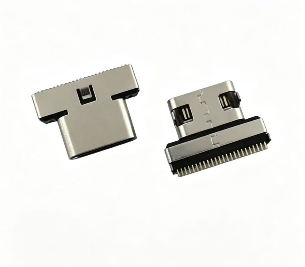
The USB4 Type-C connector landscape has evolved rapidly, and the USB-TC24-F30 represents a refined implementation of the 24-pin USB-C form factor optimized for USB4 signaling. This USB4 Type-C receptacle 24 pin is specifically designed to meet the mechanical and electrical demands of high-speed data transmission while maintaining compatibility with legacy USB standards.
Unlike many USB-C connectors that use a dual-row pin arrangement, this connector adopts a single-row SMT configuration. This design choice reduces PCB footprint and simplifies routing, making it particularly attractive for space-constrained applications such as ultra-thin laptops, mini PCs, and portable docking stations. The single-row layout also improves manufacturing yield during automated SMT assembly, as it minimizes the risk of solder bridging between adjacent pins.
From a system-level perspective, the USB-TC24-F30 is fully compatible with USB4 host controllers and retimers, supporting both Gen 2 (10Gbps per lane) and Gen 3 (20Gbps per lane) signaling modes. When paired with a certified USB4 cable, this connector enables aggregate data rates of up to 40Gbps, making it suitable for external GPUs, high-speed storage arrays, and multi-display docking solutions.
This USB4 Type-C receptacle 24 pin is not merely a passive interconnect — it is a critical enabler of modern system architectures that demand high bandwidth, low latency, and robust signal integrity. Whether you are designing a next-generation AI edge computer or a professional-grade docking station, this connector provides the electrical and mechanical foundation required for reliable USB4 operation.
24 Pin USB-C Receptacle — Full Technical Specifications
The following table provides complete electrical, mechanical, and environmental specifications for this 24 pin USB-C receptacle. All parameters are validated under standard test conditions per USB-IF and industry reliability standards.
USB4 Female Connector — Key Features
USB4 40Gbps Transmission
Engineered for high-speed differential signaling, this USB4 female connector supports USB4 Gen 3 with two lanes operating at 20Gbps each, delivering an aggregate bandwidth of 40Gbps. The optimized pin layout and controlled impedance design minimize crosstalk and insertion loss, ensuring signal integrity for demanding applications such as external GPUs and high-performance storage.
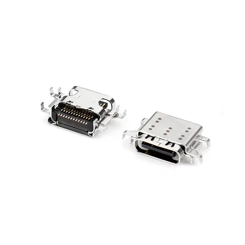
Single Row Compact Design
The single-row pin arrangement reduces PCB footprint by approximately 30% compared to dual-row designs, enabling thinner device profiles and more flexible board layouts. This USB4 female connector is ideal for ultra-slim laptops, mini PCs, and space-constrained embedded systems where every millimeter counts.
High Conductive Copper Contacts
Contacts are fabricated from high-conductivity copper alloy with gold plating, delivering low and stable contact resistance (< 30 mΩ) across the operating temperature range. This material choice minimizes signal attenuation and power loss, critical for high-frequency USB4 signaling where even small impedance variations can degrade performance.
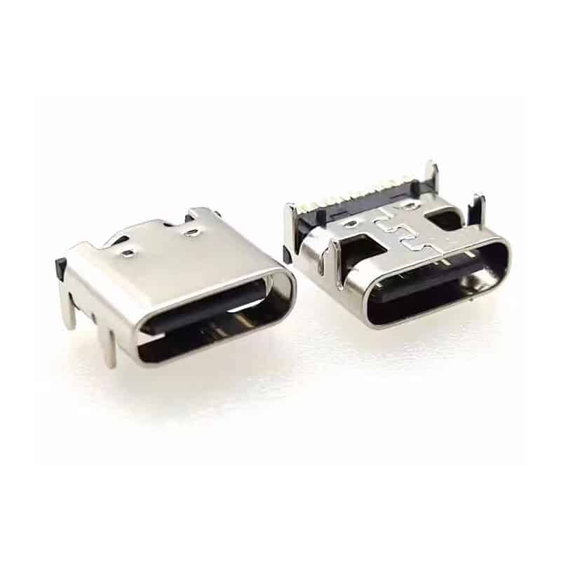
SUS304 Stainless Steel Shell
The one-piece SUS304 stainless steel shell provides robust EMI/RFI shielding, protecting sensitive USB4 signals from external interference. The material also offers excellent corrosion resistance and mechanical strength, ensuring reliable performance in industrial and medical environments where durability is paramount.
LCP High Temperature Housing
The LCP (Liquid Crystal Polymer) housing withstands peak reflow temperatures up to 260°C, making it compatible with lead-free SMT soldering processes. LCP also provides excellent dimensional stability, low moisture absorption, and high dielectric strength — essential properties for maintaining signal integrity in high-speed USB4 applications.
Automated SMT Assembly Ready
Designed for high-volume automated SMT assembly, this connector features tape-and-reel packaging, vacuum pickup compatibility, and coplanarity control. The single-row design reduces solder paste printing challenges and minimizes tombstoning risks, improving first-pass yield in production environments.
USB Type-C 24 Pin SMT Connector — USB4 Performance Advantages
As a USB Type-C 24 pin SMT connector, the USB-TC24-F30 is purpose-built to unlock the full potential of the USB4 specification. USB4 represents a paradigm shift in connectivity, combining high-speed data transfer, video output, and power delivery over a single reversible connector. Here is how this connector enables USB4 performance:
40 Gbps Aggregate Bandwidth
USB4 utilizes two lanes of high-speed differential signaling, each capable of operating at 10 Gbps (Gen 2) or 20 Gbps (Gen 3). The USB-TC24-F30 is designed with controlled differential impedance (90 Ω ± 10%) and low insertion loss (< 0.5 dB at 10 GHz) to support these signaling rates. When paired with a USB4-certified cable and host controller, this USB Type-C 24 pin SMT connector delivers a total bandwidth of 40 Gbps — sufficient for 8K video streaming, high-speed data backups, and external GPU computing.
DisplayPort Alt Mode Support
USB4 natively incorporates DisplayPort 1.4a (and later DP 2.0) Alt Mode, enabling video output over the same USB-C connection. The USB-TC24-F30 supports DP Alt Mode signaling, making it an ideal choice for docking stations, monitors, and AI edge devices that require simultaneous high-speed data and video transmission. The connector’s shielding and contact design minimize crosstalk between data and video signals.
USB Power Delivery (PD) Integration
The 24-pin configuration includes dedicated pins for power and ground, supporting USB PD up to 240W (48V/5A) with appropriate cable and controller selection. The high-conductivity copper contacts ensure minimal voltage drop under load, while the robust SUS304 shell provides reliable shielding for power delivery circuits.
Backward Compatibility with USB 3.2 / 2.0
This USB Type-C 24 pin SMT connector is fully backward compatible with USB 3.2 Gen 1 (5 Gbps), Gen 2 (10 Gbps), and USB 2.0 (480 Mbps) devices. The 24-pin receptacle includes the SuperSpeed differential pairs, USB 2.0 data lines (D+/D−), and configuration channel (CC) pins required for legacy support. This ensures seamless interoperability with existing USB peripherals while providing a migration path to USB4.
Signal Integrity Optimized Design
To maintain signal integrity at 40 Gbps, the USB-TC24-F30 incorporates several design features: controlled dielectric constant (Dk) of the LCP housing, optimized contact geometry, and a shielded shell that reduces electromagnetic interference (EMI). These features work together to maintain eye diagram margin and reduce bit error rate (BER) in high-speed USB4 systems.
Technical Note: The connector itself supports USB4 40 Gbps signaling, but the final system data rate depends on the host controller, cable quality, PCB layout, and overall system design. For optimal performance, follow the PCB design guidelines provided in the PCB Design Considerations section below.
Material Advantages — High Conductive Copper, 304 Stainless Steel & LCP
The USB-TC24-F30 is built from three carefully selected materials, each contributing to the connector’s performance, reliability, and manufacturability. Understanding these material choices helps engineers select the right interconnect for their application.
High Conductive Copper Contacts
Contact performance is the single most important factor affecting signal integrity in high-speed connectors. The USB-TC24-F30 uses a high-conductivity copper alloy (CuCrZr or similar) with a gold-plated finish. Key advantages include:
- Low Contact Resistance: < 30 mΩ initial, ensuring minimal signal loss and voltage drop.
- High Conductivity: ≥ 80% IACS (International Annealed Copper Standard), reducing heat generation at high currents.
- Gold Plating: Provides oxidation resistance, stable contact interface, and supports 10,000+ mating cycles.
- Spring Retention: The copper alloy maintains spring force over temperature and mechanical cycling, ensuring consistent contact pressure.
SUS304 Stainless Steel Shell
The one-piece outer shell is fabricated from SUS304 stainless steel, a material widely used in electronic connectors for its combination of strength, corrosion resistance, and formability. Benefits include:
- EMI/RFI Shielding: The conductive shell provides a continuous shield that attenuates electromagnetic interference, critical for USB4’s high-frequency signals.
- Corrosion Resistance: SUS304 withstands humidity, salt spray, and industrial atmospheres, making it suitable for medical and industrial applications.
- Mechanical Strength: The shell resists deformation during cable insertion and extraction, maintaining connector geometry over thousands of cycles.
- Grounding: The shell provides a low-impedance ground path, improving ESD protection and system noise immunity.
LCP High Temperature Housing
Liquid Crystal Polymer (LCP) is the housing material of choice for high-speed SMT connectors. Its properties are particularly well-suited to USB4 applications:
- High Temperature Resistance: Withstands 260°C peak reflow temperatures, compatible with lead-free soldering profiles.
- Dimensional Stability: Low coefficient of thermal expansion (CTE) ensures pin coplanarity and alignment through the soldering process.
- Low Dielectric Constant: Dk ≈ 3.0–3.5 at high frequencies, minimizing signal propagation delay and maintaining impedance control.
- Low Moisture Absorption: < 0.1% absorption prevents blistering during reflow and maintains electrical properties in humid environments.
- UL 94V-0 Flammability Rating: Meets safety requirements for consumer and industrial electronics.
Together, these three materials — high-conductivity copper, SUS304 stainless steel, and LCP — create a connector that balances electrical performance, mechanical durability, and manufacturing compatibility. This material combination is validated through extensive reliability testing, including thermal shock, humidity exposure, and mechanical cycling per EIA-364 standards.
Applications for AI, Mini PC, Docking Stations & Industrial Systems
AI Edge Computer
High-speed data transfer for AI inference & training
Docking Station
Multi-display & data hub for laptops
Mini PC
Compact form-factor computing
Notebook
Ultra-thin laptops with USB4 ports
Medical Equipment
Diagnostic & imaging systems
Industrial Controller
Factory automation & PLC
Embedded Computer
IoT gateways & embedded systems
POS Terminal
Retail & hospitality payment systems
Smart Display
Digital signage & interactive kiosks
Portable SSD
High-speed external storage
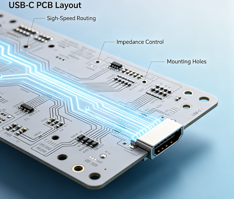
PCB Design Considerations for High-Speed USB4 Layout
Designing a PCB for USB4 40 Gbps operation requires careful attention to layout, impedance control, and grounding. The following guidelines are recommended when using the USB-TC24-F30 or any USB4 Type-C receptacle 24 pin in high-speed applications.
Keep-Out Area & Component Placement
Ensure a keep-out zone around the connector footprint to avoid interference from adjacent components. Allow at least 2 mm clearance on all sides for reflow soldering and inspection. Place the connector near the PCB edge to minimize cable overhang and mechanical stress. For horizontal (right-angle) mounting, the connector body should extend beyond the PCB edge per the mechanical drawing.
Ground Connection & Return Path
Provide a low-impedance ground connection for the connector’s shell and shield tabs. Use multiple ground vias (at least 4–6 vias) placed close to the shield solder tabs to minimize ground inductance. The ground plane should be continuous beneath the connector area, with no splits or slots that could create impedance discontinuities.
Shield Solder Tabs
The USB-TC24-F30 includes shield solder tabs on both sides. Solder these tabs to the PCB ground plane using a thermal relief pattern to balance solderability and heat dissipation. Ensure the solder pads are sized according to the manufacturer’s footprint recommendations to avoid tombstoning or insufficient wetting.
Differential Pair Routing
Route USB4 SuperSpeed differential pairs (Tx1+/Tx1−, Tx2+/Tx2−, Rx1+/Rx1−, Rx2+/Rx2−) with controlled differential impedance of 90 Ω ± 10%. Maintain consistent trace spacing (S) and width (W) throughout the routing path. Use ground stitching vias alongside differential pairs to provide a continuous return path and reduce crosstalk. Keep trace length mismatches within the pair below 0.5 mm (5 mils) to maintain skew tolerance.
ESD Protection
Place ESD protection devices (e.g., TVS diodes) as close as possible to the connector pins, especially on the USB 2.0 (D+/D−) and configuration channel (CC1/CC2) lines. For SuperSpeed differential pairs, use low-capacitance ESD devices (< 0.5 pF) to preserve signal integrity. Follow the USB4 ESD protection guidelines and consider adding series resistors (0 Ω or small values) for additional protection.
Reflow Profile Recommendations
Given the LCP housing, the USB-TC24-F30 is compatible with standard lead-free reflow profiles. Recommended reflow parameters: peak temperature 245–260°C, time above 217°C: 60–90 seconds, ramp rate: 1–2°C/sec. Avoid exceeding 260°C to prevent housing discoloration or deformation. Pre-baking is not required for LCP, but ensure components are stored in dry conditions per IPC/JEDEC J-STD-033.
Pro Tip: For optimal USB4 performance, consider using a 4-layer or 6-layer PCB stack-up with dedicated ground and power planes. The reference plane should be continuous beneath the differential pairs, and vias should be kept to a minimum to reduce stub effects.
How to Choose the Right USB4 Type-C 24 Pin Connector
Selecting the correct USB Type-C connector for your application involves understanding your system’s data rate, power, and mechanical requirements. Here is a decision framework to help you choose the right USB4 Type-C receptacle 24 pin for your design.
Step 1: Identify Your Data Rate Requirements
- USB 2.0 (480 Mbps): A 4-pin or 6-pin USB-C connector may suffice. No need for 24 pins.
- USB 3.2 Gen 1 (5 Gbps): A 16-pin connector with SuperSpeed pairs is required. 24-pin is optional.
- USB 3.2 Gen 2 (10 Gbps): Full 24-pin connector with low insertion loss and controlled impedance is recommended.
- USB4 (20–40 Gbps): A high-quality 24 pin USB-C receptacle with optimized shielding and contact design is mandatory. The USB-TC24-F30 is specifically engineered for this tier.
Step 2: Evaluate Power Delivery Needs
- Standard USB Power (5V/0.5A–1.5A): Basic 4-pin or 6-pin connector may work.
- USB PD (up to 100W): Requires 24-pin connector with dedicated VBUS and GND pins, plus CC1/CC2 for PD negotiation.
- USB PD 3.1 (up to 240W): 24-pin connector with robust contacts and low contact resistance is essential. The USB-TC24-F30’s high-conductivity copper contacts support extended power delivery.
Step 3: Consider Video Output (DisplayPort Alt Mode)
- No video output: A 16-pin or 24-pin connector without DP Alt Mode support may be acceptable.
- DP Alt Mode (4K/8K): Requires a USB4 Type-C connector with full 24-pin configuration, supporting the four SuperSpeed lanes used for video data.
Step 4: Assess Mechanical Constraints
- Board Space: If PCB area is limited, a single-row SMT connector like the USB-TC24-F30 offers a compact footprint.
- Mounting Type: Choose SMT for high-volume automated assembly or DIP (through-hole) for prototyping and extreme mechanical reliability. The USB-TC24-F30 is SMT-optimized.
- Orientation: Horizontal (right-angle) for edge-mounted ports; vertical for top-down insertion. The USB-TC24-F30 is a horizontal connector.
Step 5: Confirm Environmental and Reliability Requirements
- Operating Temperature: −40°C to +85°C (industrial) or −25°C to +70°C (commercial). The USB-TC24-F30 covers industrial ranges.
- Mating Cycles: 5,000 cycles for consumer devices; 10,000+ for industrial or docking applications. The USB-TC24-F30 supports 10,000+ cycles.
- Moisture & Corrosion: For medical or outdoor applications, the SUS304 shell and gold-plated contacts provide excellent resistance.
If your application requires high-speed data (40 Gbps), video output, and power delivery in a compact single-row SMT package, the USB-TC24-F30 is a strong candidate. Always review the full datasheet and PCB footprint before finalizing your design.
USB4 Type-C 24 Pin Connector — Frequently Asked Questions
What is a USB4 Type-C receptacle?
A USB4 Type-C receptacle is a 24-pin female connector that implements the USB4 specification over the USB Type-C form factor. It supports data rates up to 40 Gbps, DisplayPort Alt Mode, USB Power Delivery, and backward compatibility with USB 3.2 and USB 2.0. The USB-TC24-F30 is a USB4 Type-C receptacle designed for SMT mounting in high-speed applications.
Does this connector support 40 Gbps data rate?
The USB-TC24-F30 is designed and validated for USB4 40 Gbps operation. However, the final data rate in your system depends on the entire signal chain — including the host controller, cable, PCB layout, and whether the system is designed to USB4 Gen 3 (20 Gbps per lane) standards. For guaranteed 40 Gbps performance, ensure all components in the path are USB4-certified and the PCB follows high-speed design guidelines. Refer to the USB-IF USB4 Specification for official requirements.
Is it compatible with USB 3.2 and USB 2.0?
Yes. The USB-TC24-F30 includes all necessary pins for USB 3.2 (SuperSpeed differential pairs) and USB 2.0 (D+/D−). When used with a USB 3.2 host controller and cable, the connector supports up to 10 Gbps (Gen 2) data rates. For USB 2.0, it supports 480 Mbps. The connector automatically negotiates the highest mutually supported speed with the connected device.
Can it support USB Power Delivery (PD)?
Yes. The 24-pin configuration includes dedicated VBUS and GND pins, plus CC1/CC2 for PD negotiation. The high-conductivity copper contacts minimize voltage drop under load, and the connector is rated for the current levels required by USB PD (up to 5A with appropriate PCB traces and controller). The connector itself does not regulate power — that is handled by the PD controller — but it provides the necessary electrical path.
What PCB thickness is recommended?
The USB-TC24-F30 is compatible with standard PCB thicknesses of 0.8 mm, 1.0 mm, and 1.6 mm. The SMT pads are designed to accommodate these thicknesses. For optimal mechanical stability, a PCB thickness of 1.6 mm is recommended for most applications, while 1.0 mm is preferred for ultra-thin devices. Always verify the mechanical drawing for specific clearance and keep-out requirements.
Is it suitable for automated SMT assembly?
Absolutely. The USB-TC24-F30 is designed for high-volume SMT assembly. It is supplied in tape-and-reel packaging, features a flat top for vacuum pick-and-place, and has coplanarity control to ensure consistent soldering. The single-row design simplifies solder paste printing and reduces the risk of bridging. Standard reflow profiles with peak temperatures up to 260°C are supported.
Can I customize the shell or housing color?
Customization options are available for OEM orders. The shell can be plated with different finishes (e.g., nickel, gold), and the housing can be molded in custom colors for brand differentiation. Minimum order quantities (MOQ) apply for customizations. Contact our sales team to discuss your specific requirements.
Is OEM / ODM available?
Yes. We offer full OEM and ODM services for the USB-TC24-F30 and other USB Type-C connectors. This includes custom part numbering, packaging, labeling, and design modifications to meet specific application requirements. Whether you need a minor tweak or a full custom design, our engineering team can support your project. Contact us to discuss your OEM/ODM needs.
What is the MOQ for the USB-TC24-F30?
The standard MOQ for the USB-TC24-F30 is 1,000 pieces for standard configurations. Lower MOQs may be available for engineering samples or prototyping. For high-volume production orders (10,000+ pieces), we offer competitive pricing and reduced lead times. Please request a quote for your specific volume requirements.
Can I request free samples?
Yes. Free samples of the USB-TC24-F30 are available for qualified engineering and product development projects. We understand that evaluating components before committing to production is essential. To request samples, please provide your company name, project details, and estimated volume. Click the “Request Sample” button at the top of this page or contact us directly.

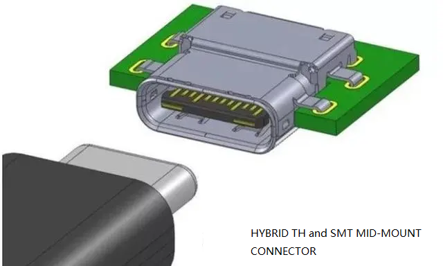
Mid mount usb c receptacle pinout type-c 24 Pin connector SMT CL=0.5MM l=8.21mm
24 Pin USB-C Connector Female SMT | USB 4.0 Type-C Receptacle | Vistar Electronics

USB 3.2 Gen 2 Type-C Connector 24 Pin for 10Gbps High-Speed & Fast Charging Devices
USB C 16 pin connector — USB 3.1 Type-C Female Right Angle PCB Mount (USB-TC16-F01)

24 pin Vertical USB-C SMT Connector

USB Type C Surface Mount Connector 16P — USB-TC16-F04 16 Pin SMD Horizontal Receptacle with 5A Rating

PCB mount Connector USB Type C female 24 pin SMT horizontal CL=1.57 L=9.17

USB 3.2 Gen 2 Type-C Connector 24 Pin SMT Female Receptacle for 10Gbps High-Speed Devices
USB-C PCB Layout Design Guide for High-Speed PCB Applications
Master USB-C PCB layout with 12 essential design rules covering differential pair routing, impedance control, power delivery, and ESD protection. Practical engineering...

USB-C Connector Types Explained: A Complete Guide for Engineers and Buyers
If you’re a hardware engineer or sourcing professional selecting USB-C connectors for your next PCB design, understanding the different USB-C connector types...
The Ultimate USB-C Mid Mount Connector Design Guide: 8 Engineering Tips for Ultra-Thin Devices
Learn how to select the right USB-C mid mount connector for ultra-thin devices. Compare mounting styles, PCB layout requirements, power delivery, and...