

USB-C Receptacle 24 Pin Mid-Mount — USB-TC24-F11 SMT Mid-Mount USB-C 24-Pin Jack for Ultra-Thin Laptops, Tablets & IoT Devices
The USB-TC24-F11 is a USB-C receptacle 24 pin mid-mount — a full‑featured 24‑pin SMT mid‑mount USB Type‑C female connector, rated 3A, 10,000 mating cycles, USB 3.2 Gen 2 (10 Gbps) compliant. Designed for PCB cutout mounting in ultra‑thin enclosures, it supports Power Delivery up to 100W, DisplayPort Alt Mode, and reversible plug orientation. RoHS & REACH compliant. Tape & Reel packaging. MOQ 1,000 pcs. Free sample available for qualified projects.
USB-TC24-F11 USB-C Receptacle — 24 Pin Mid-Mount USB-C Connector Product Overview
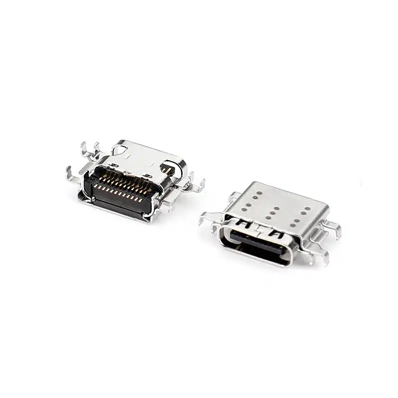
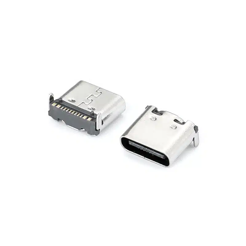
The USB-TC24-F11 USB-C receptacle is a 24‑pin mid‑mount SMT USB Type‑C connector engineered for next‑generation ultra‑slim devices. Its mid‑mount design places the receptacle mouth precisely within a PCB cutout, reducing overall height above the board to nearly zero. This USB-C receptacle 24 pin mid-mount enables device enclosures as thin as 5mm, making it the preferred choice for modern laptops, tablets, AR/VR headsets, and IoT sensor modules where every fraction of a millimeter counts.
Despite its low profile, the connector delivers full USB 3.2 Gen 2 performance with all 24 pins available: SuperSpeed TX/RX pairs, sideband (SBU), configuration channel (CC), and multiple VBUS/GND returns. It supports USB Power Delivery up to 100W (20V/5A), DisplayPort Alternate Mode, and backward compatibility with USB 2.0. A stainless steel mid‑plate inside the receptacle tongue provides mechanical robustness against daily plug insertions, while gold‑plated contacts maintain a stable connection over the product’s lifetime. Designed for automated SMT assembly, the USB-TC24-F11 comes in tape‑and‑reel packaging and withstands lead‑free reflow temperatures up to 260°C.
24 Pin Mid-Mount USB-C Receptacle SMT — Full Technical Specifications
| Parameter | Value | Notes |
|---|---|---|
| Part Number | USB-TC24-F11 | Standard catalog item |
| Connector Type | USB Type‑C Receptacle | Female, 24‑pin, full‑featured |
| USB Standard | USB 3.2 Gen 2 (10 Gbps) | Backward compatible USB 2.0/3.0 |
| Pin Count | 24 Pins (SMT) | All signals: SSTX, SSRX, CC, SBU, VBUS, GND |
| Mounting Style | SMT Mid‑Mount | PCB cutout required |
| Orientation | Horizontal (Mid‑Mount) | Receptacle tongue centered in board cutout |
| Current Rating | 3A per VBUS contact (5A total) | Supports USB PD up to 100W |
| Voltage Rating | 20V DC max | Per USB PD 3.0 specification |
| Mating Cycles | 10,000 cycles | Stainless steel mid‑plate reinforced |
| Insertion Force | 5–20 N | Typical Type‑C range |
| Withdrawal Force | 8–20 N | Per USB‑IF mechanical standard |
| Contact Material | Phosphor Bronze, Gold 30µ” over Nickel | Low contact resistance |
| Mid‑Plate Material | Stainless Steel | EMI shielding & mechanical strength |
| Shell Material | Stainless Steel, Nickel Plated | Corrosion‑resistant |
| Housing Material | LCP (UL94 V‑0), high‑temp | Reflow 260°C compatible |
| Differential Impedance | 85–100 Ω (nominal 90 Ω) | Per USB 3.2 specification |
| Contact Resistance | ≤40 mΩ initial | After 10,000 cycles ≤80 mΩ |
| Insulation Resistance | ≥100 MΩ @ 100V DC | Between adjacent contacts |
| Dielectric Strength | 100V AC (1 minute) | No breakdown |
| Operating Temperature | −30°C to +85°C | Commercial & light‑industrial |
| Storage Temperature | −40°C to +90°C | — |
| Soldering Profile | Reflow 260°C, 10s max | Per JEDEC J‑STD‑020, MSL 1 |
| Packaging | Tape & Reel (800 pcs/reel) | 13‑inch reel, antistatic |
Why Engineers Choose the Mid-Mount USB-C 24 Pin Receptacle 3A — Key Advantages
Ultra‑Low Profile with Mid‑Mount Design
The connector sits within a PCB cutout, placing the receptacle tongue nearly flush with the board surface. This mid-mount USB-C 24 pin receptacle 3A enables device enclosures to be up to 3mm thinner than those using conventional top‑mount connectors, crucial for premium tablets and slim IoT gateways.
Full 24‑Pin USB 3.2 Gen 2 & 100W Power Delivery
All SuperSpeed lanes and CC/SBU pins are available, allowing simultaneous 10 Gbps data, DisplayPort video output, and USB PD up to 100W — all through a single reversible connector.
Reinforced Stainless Steel Mid‑Plate
A full‑length stainless steel mid‑plate inside the tongue dramatically increases resistance to bending and insertion abuse, guaranteeing 10,000 mating cycles without degradation. It also provides a robust ground reference.
RoHS 3 & REACH Compliant, Reflow‑Ready
Fully compliant with RoHS 3 (2015/863) and REACH SVHC. The LCP housing and precise terminal coplanarity (≤0.08mm) ensure high‑yield SMT assembly. For regulatory details, see the ECHA REACH regulation. USB compliance info can be found at USB-IF.
Where to Use the USB-C Female Receptacle 24 Pin Mid-Mount PCB — Applications for Mobile, IoT & Industrial
PCB Cutout Layout & SMT Assembly Guidelines for the 24-Pin Mid-Mount USB-C Receptacle
PCB Cutout Dimensions
The USB-TC24-F11 requires a precisely routed rectangular cutout in the PCB. Recommended cutout size: 8.40mm × 4.90mm. Maintain a minimum web thickness of 2.0mm from the cutout edge to the nearest board outline to prevent breakage during depaneling. The connector’s locating pegs will self‑align the part into the cutout during placement.
High‑Speed Signal Routing
All SuperSpeed differential pairs (TX1±, RX1±, TX2±, RX2±) must be length‑matched within 5 mil and impedance‑controlled to 90 Ω ±10%. Place ESD protection diodes as close as possible to the connector pads. Route VBUS and GND with wide traces or polygons to handle 5A continuous current with minimal voltage drop.
SMT Stencil & Reflow
Use a 0.1mm or 0.12mm thick laser‑cut stainless steel stencil with aperture openings reduced to 80% of pad area for fine‑pitch signal pads. Type 4 SAC305 lead‑free solder paste is recommended. The connector is MSL 1 and requires no pre‑bake. Peak reflow temperature should reach 245–260°C with a time above 217°C of 60–90 seconds. After soldering, inspect for coplanarity and ensure no bridging on the fine‑pitch pads.
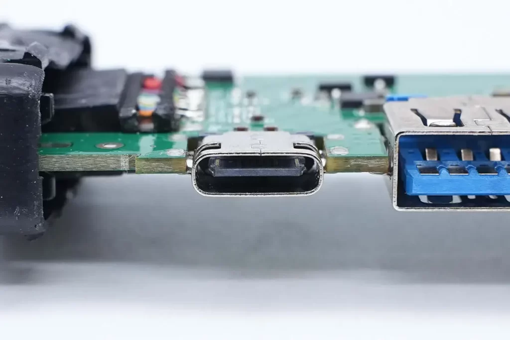
Mid-Mount vs Top-Mount vs Vertical USB-C Connectors: Choosing the Right Orientation for Thin Designs
When every millimeter of device thickness matters, the USB-C receptacle 24 pin mid-mount offers a decisive advantage. A top‑mount connector sits entirely above the PCB, adding at least 2.0mm to the product stack‑up. A vertical connector extends upward, requiring the board to be placed at the device edge. The mid‑mount approach, however, embeds the connector body into a PCB cutout, making the receptacle tongue nearly flush with the board surface. This allows the enclosure to close tightly around the connector without a bulge, enabling industrial designs as thin as 5mm.
Mechanically, the mid‑mount design also strengthens the assembly. Because the shell is soldered to both top and bottom PCB pads and braced by the board thickness itself, lateral stresses from cable plugging are distributed into the PCB rather than concentrated on the solder joints. This reduces the risk of pad lifting or shell detachment over thousands of insertions — a common failure point in top‑mount connectors used in portable devices. For ultra‑slim laptops, tablets, and wearables, the mid‑mount USB-C connector is the definitive solution for full‑featured, robust connectivity.
Reliability Testing & Compliance for the 24-Pin Mid-Mount USB-C Jack
The USB-TC24-F11 has passed a rigorous qualification program that guarantees 10,000 insertion cycles and compliance with USB‑IF mechanical and environmental standards. Key test results include:
- Mating Durability: 10,000 insertion/extraction cycles at 200 cycles/hour with a certified USB Type‑C plug. Contact resistance stayed below 80 mΩ, and no physical damage was observed on the tongue.
- 4‑Axis Mechanical Stress: Withstood a 15 N side‑pull force applied 2 mm from the receptacle face for 60 seconds in all four directions. Solder joints and shell tabs remained intact.
- High‑Speed Signal Integrity: Tested with USB 3.2 Gen 2 (10 Gbps) compliance patterns. Eye‑diagram opening exceeded minimum USB‑IF mask requirements at both 5 Gbps and 10 Gbps after 10,000 cycles.
- Thermal Shock: 200 cycles between −40°C and +85°C per IEC 60068‑2‑14. No solder joint cracks detected via X‑ray inspection, and contact resistance drift was less than 10 mΩ.
- Mixed Flowing Gas: 96‑hour Class II exposure per IEC 60068‑2‑60. Gold plating protected contacts from corrosion; low‑level contact resistance remained below 50 mΩ.
For a complete test report or to discuss custom qualification, contact engineering@vistarelectronics.com.
Packaging, Compliance & Ordering Information
All USB-TC24-F11 USB-C receptacle units are shipped in sealed dry‑pack tape & reel (800 pieces per 13‑inch reel) with MSL 1 designation, eliminating the need for pre‑baking. The connector is lead‑free and fully compatible with SAC305 solder. Customizations including higher gold thickness (up to 50µ”), alternative shell plating, or IP67 sealing gaskets are available on request. Standard MOQ is 1,000 pieces. To request a free sample or volume price, email sales@vistarelectronics.com with your company details and project description.
USB-C Receptacle 24 Pin Mid-Mount — Frequently Asked Questions
Does the USB-TC24-F11 support USB Power Delivery (PD) up to 100W?
Yes. The connector is rated for 3A per VBUS contact (with four VBUS pins total), providing a 5A capacity when properly paralleled. This, combined with the CC pins and 20V insulation rating, makes it suitable for USB PD 3.0 up to 100W (20V/5A). The PD controller and power path management must be implemented externally on your board.
Can I use this connector for USB 2.0 only designs and leave high‑speed pairs unconnected?
Yes. You can use only the D+, D−, VBUS, GND, and CC pins for a USB 2.0 or charging‑only design. Unused SuperSpeed and SBU pads can be left as no‑connects, though it is recommended to connect all GND pins to the ground plane for mechanical robustness.
What is the recommended PCB thickness for this mid‑mount connector?
The connector is optimized for 1.0mm and 1.2mm thick PCBs, which are common in ultra‑thin devices. It can also work with 0.8mm or 1.6mm boards if the stencil and cutout tolerances are adjusted accordingly.
Is a free sample available for prototyping?
Absolutely. We provide free samples to qualified engineering teams. Send your request to sales@vistarelectronics.com with your company name, project application, and the part number USB-TC24-F11. Standard MOQ for production orders is 1,000 pieces.
How do I ensure the connector stays aligned during reflow soldering?
The USB-TC24-F11 has two locating pegs that sit in corresponding plated holes or slots in the PCB cutout. These pegs, combined with the coplanarity‑controlled terminals, keep the connector stable during reflow. We recommend verifying the paste deposit volume on the anchor pads is sufficient to form a proper fillet.

USB C Connector female 24 pin top mount right angle
Best USB C 16 Pin DIP Vertical Connector | 5A Through-Hole Type-C Female H=6.5mm | USB-TC16-F09

USB 3.1 Type-C Connector 24 Pin for High-Speed Data and Power Applications

PCB mount Connector USB Type C female 24 pin SMT horizontal CL=1.57 L=9.17
24 Pin USB-C Connector Female SMT | USB 4.0 Type-C Receptacle | Vistar Electronics
USB-C 16 Pin SMT On-Board Connector for USB Power Delivery & Compact High-Density PCB Design

USB Type-C Receptacle Connector 24 Pin SMD – 10Gbps High‑Reliability Solution

USB Type C connector on motherboard 14 pin
Automotive USB-C Connectors for Modern Vehicle Systems
You have a USB-C port that works flawlessly on your smartphone. You drop it into a dashboard mount in a vehicle—and within...
Industrial USB-C Connector: A Complete Guide for Harsh Environment Applications
Industrial systems are rapidly adopting USB-C as the standard interface for data, power, and control. But consumer-grade USB-C connectors fail quickly in...

USB-C Connector Selection Guide: How to Choose the Right Connector for Your Design
Master usb-c connector selection guide. Compare pin counts, mounting styles, waterproof ratings and power delivery specs for reliable PCB design. USB-C has...