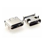
A USB PD connector is not simply a USB-C receptacle with a higher current rating. For a USB Power Delivery design, the connector must match the required voltage, current, CC configuration, mating cycles, PCB layout and, for USB PD 3.1 EPR applications, the electrical requirements associated with operation up to 48V and 240W.
Most design reviews focus on the PD controller IC, the firmware stack, and the power negotiation protocol. The connector is treated as a commodity — a passive component that “just needs to fit.” That assumption holds until the first prototype fails EPR negotiation, or the connector overheats at 5A continuous, or the CC pins short to a 48V VBUS rail during a hot-plug event.
This guide focuses specifically on the USB PD connector — the physical interface that carries the power. It covers USB PD 3.1, EPR voltage levels, 6/16/24-pin selection, SMT vs DIP mounting, and the mechanical and electrical parameters that determine whether a PD design works reliably in production.

For the protocol-level details of USB Power Delivery, including PDO negotiation and SPR/EPR architecture, see the USB Power Delivery Guide: Critical USB PD Protocol & USB-C Design.
Need a USB PD Connector Matched to Your Design?
Vistar Electronics supplies USB-C receptacles engineered for USB PD applications — including 6-pin power-only, 16-pin USB 2.0 + PD, and 24-pin full-featured designs. SMT, DIP, and hybrid mounting. 5A-rated contacts. Up to 10,000 mating cycles. RoHS 3 & REACH compliant. MOQ 1,000 pcs. Free samples available.
What Is a USB PD Connector?
A USB PD connector is the physical USB-C receptacle that carries USB Power Delivery signals and power. It must support:
- VBUS — Power delivery up to 48V (EPR) or 20V (SPR)
- GND — Ground return path
- CC1/CC2 — Configuration Channel for PD negotiation
- D+/D− — USB 2.0 data (for 16-pin and 24-pin connectors)
The PD protocol itself is implemented by a controller IC on the PCB. The connector’s job is to carry the resulting voltages and currents without degradation, overheating, or failure.
The critical distinction: USB-C is the connector standard. USB PD is the power delivery protocol that runs over it. A USB-C connector can exist without PD support. A PD design cannot exist without a connector rated for the voltages and currents the protocol negotiates.
Because USB PD operates through the USB Type-C ecosystem, connector selection should also be checked against the USB Type-C Cable and Connector Specification from USB-IF.
USB PD 3.1: What Changed?
USB PD 3.1 introduced the Extended Power Range (EPR), expanding the maximum power from 100W to 240W.
| Specification | USB PD 3.0 (SPR) | USB PD 3.1 (EPR) |
|---|---|---|
| Max Voltage | 20V | 48V |
| Max Current | 5A | 5A |
| Max Power | 100W | 240W |
| Voltage Levels | 5V, 9V, 15V, 20V | 5V, 9V, 15V, 20V, 28V, 36V, 48V |
| Cable Requirement | 5A rated | 5A rated + EPR rated |
| E-Marker | Required for >3A | Required for >3A |
EPR adds three new fixed voltage levels — 28V, 36V, and 48V — all at 5A maximum current. The 48V rail represents the practical safety limit for the connector, considering design margins and creepage requirements.
For the official USB Power Delivery requirements and protocol details, see the USB Power Delivery Specification published by the USB Implementers Forum (USB-IF).
The key implication for connector selection: a USB PD 3.1 EPR connector must be rated for 48V VBUS operation, not just 20V. This is not a trivial upgrade. The connector’s insulation material, pin spacing, creepage distance, and contact geometry must all support the higher voltage.
USB PD Connector Requirements
The following parameters determine whether a USB-C connector is suitable for a PD application:
1. Voltage Rating
The connector must be rated for the maximum VBUS voltage in the PD contract:
- SPR only (up to 100W): 20V minimum
- EPR (up to 240W): 48V minimum
A connector rated for 20V operation is not necessarily safe for 48V EPR. Check the manufacturer’s voltage rating explicitly.
2. Current Rating
USB PD uses up to 5A on VBUS. The connector’s VBUS contacts must be rated for continuous 5A operation without exceeding the temperature rise limit. Contact resistance and thermal design determine whether the connector can sustain 5A continuously.
3. CC Pin Configuration
The CC1 and CC2 pins carry the PD negotiation signals. The connector must expose both CC pins. In EPR designs, CC pins must also withstand potential short-circuit events with the 48V VBUS rail.
4. Contact Plating
Gold plating is recommended for high-reliability PD connectors. It resists oxidation and maintains low contact resistance over thousands of mating cycles, which is critical at 5A current.
5. Mating Cycles
A USB PD connector for a frequently used charging port should be rated for at least 5,000 cycles, preferably 10,000 cycles for industrial or docking applications.
6. Mounting Style
SMT, DIP, or hybrid mounting determines the mechanical strength of the connector-to-PCB interface. For external PD ports subject to repeated insertion, through-hole or hybrid mounting is preferred.
6-Pin vs 16-Pin vs 24-Pin USB-C for PD
The pin count determines what the connector can do beyond power delivery.
| USB-C Connector | PD Capability | USB Data | USB 3.x/USB4 | Typical Use |
|---|---|---|---|---|
| 6-pin | Charging-focused | No | No | Power-only devices |
| 16-pin | Yes | USB 2.0 | No | Charging + USB 2.0 |
| 24-pin | Yes | USB 2.0 | Yes | Laptop, dock, monitor |
6-pin connectors populate only VBUS, GND, and CC pins. They are the simplest and lowest-cost option for power-only applications. They can negotiate PD contracts, but cannot carry any USB data.
16-pin connectors add USB 2.0 data lines (D+/D−). They support PD charging and USB 2.0 communication. This is the most common configuration for devices that need PD power plus basic data, such as microcontrollers, peripherals, and embedded systems. Vistar’s USB-TC16-F09 is a 16-pin DIP vertical connector supporting CC1/CC2, USB 2.0, and 5A/30VDC operation.
24-pin connectors expose all USB-C pins, including SuperSpeed differential pairs, SBU sideband pins, and full PD support. They are required when the design needs USB 3.x/USB4 data or DisplayPort Alt Mode alongside PD power.
Critical point: Pin count alone does not guarantee a specific PD power level. The connector’s voltage rating, current rating, and contact design determine what PD contract it can support. A 16-pin connector rated for 5A and 48V can handle 240W EPR, while a 24-pin connector rated for only 3A cannot exceed 100W.
For a detailed pin-by-pin reference, see the USB-C Connector Pinout Explained: 24P to 6P Complete Guide.
USB PD 3.1 Connector: What Changes at 240W?
Moving from 100W SPR to 240W EPR is not simply a matter of using a different PD controller. The connector itself faces new electrical and thermal requirements.
Voltage withstand: The connector must safely carry 48V on VBUS. The insulation between VBUS and adjacent pins (CC, SBU, D+) must prevent arcing and leakage. Connectors designed only for 20V may have insufficient creepage distance for 48V operation.
Contact resistance: At 5A continuous current, every milliohm of contact resistance contributes to heat generation. The connector’s contact geometry, plating, and spring force must maintain low resistance over the product’s service life.
Thermal performance: A 240W connector dissipates more heat than a 100W connector. The housing material must maintain mechanical integrity at elevated temperatures, and the PCB copper area around the VBUS pads must be sufficient to conduct heat away from the connector.
CC and SBU protection: The CC1/CC2 and SBU1/SBU2 pins are physically adjacent to VBUS. At 48V, a short between VBUS and CC — caused by mechanical distortion, moisture, or debris — can destroy the PD controller. EPR designs typically require port protection devices that can withstand 48V on the CC and SBU pins.
SMT vs DIP USB PD Connectors
The mounting style affects mechanical reliability, assembly cost, and PCB layout.
| Factor | SMT | DIP (Through-Hole) | Hybrid (SMT + THT) |
|---|---|---|---|
| Mechanical Strength | Moderate | Excellent | Excellent |
| PCB Space | High density | Lower density | Moderate |
| Assembly | Reflow only | Wave/selective solder | Mixed process |
| Plug-in Stress | Limited cycles | High cycles | High cycles |
| Best For | Compact devices | External PD ports | High-reliability designs |
SMT connectors are the standard choice for compact, high-volume consumer devices where the PD port is used primarily for charging and the mechanical stress is moderate.
DIP (through-hole) connectors are preferred for external PD ports that endure frequent insertion and extraction. The through-hole leads anchor the connector to the board, distributing insertion force across the PCB thickness.
Hybrid connectors combine SMT signal contacts with through-hole retention tabs. The SMT contacts carry high-speed signals with low parasitics, while the through-hole tabs provide mechanical strength. This architecture is common in high-reliability PD designs.
For a detailed comparison of mounting technologies, see USB C SMT vs Through Hole: 7 Critical PCB Differences.
PCB Layout Considerations for USB PD Connectors
A correct connector selection can still fail if the PCB layout does not support the PD design.
VBUS copper: The VBUS traces and pads must be sized for 5A continuous current. For 1oz copper, a minimum width of 100 mil (2.54 mm) is typically required for 5A with acceptable temperature rise. Use multiple VBUS pins in parallel where the connector provides them.
CC routing: Route CC1 and CC2 as short, direct traces to the PD controller. Keep them away from switching nodes and high-current paths. Add ESD protection near the connector if the design requires it.
Ground plane: Maintain a continuous ground plane beneath the connector. The GND pins should connect to the plane with short, wide traces to minimize return path impedance.
Thermal relief: For EPR designs, consider adding thermal vias beneath the VBUS pads to conduct heat into internal copper layers. This reduces connector temperature rise at 5A continuous current.
For a comprehensive guide on USB-C PCB layout, see Complete Design Guide for Choosing a USB-C Connector: From Pin Configuration Selection to PCB Layout and Routing.
Common USB PD Connector Mistakes
Mistake 1: Assuming every USB-C connector supports 240W. A connector may be physically USB-C but rated only for 20V or 3A. Always check the voltage and current ratings explicitly.
Mistake 2: Using a 20V-rated connector in a 48V EPR design. The creepage and clearance requirements for 48V are different. A connector that works at 20V may fail at 48V due to insufficient insulation.
Mistake 3: Ignoring CC pin protection. At 48V, a VBUS-to-CC short can destroy the PD controller. EPR designs should include port protection devices.
Mistake 4: Selecting the connector by pin count only. A 16-pin connector with 5A contacts can handle more PD power than a 24-pin connector with 3A contacts.
Mistake 5: Not validating thermal performance at 5A. A connector that passes continuity testing at 1A may overheat at 5A continuous. Test the actual thermal performance under load.
How to Select a USB PD Connector for Production
Before requesting a quotation, define these parameters:
- PD version — PD 3.0 (SPR) or PD 3.1 (EPR)
- Maximum power — 60W, 100W, or 240W
- Maximum voltage — 20V or 48V
- Maximum current — 3A or 5A
- Pin count — 6, 16, or 24 pins
- Data requirement — None, USB 2.0, or USB 3.x/USB4
- Mounting style — SMT, DIP, or hybrid
- Mating cycles — 5,000 or 10,000
- Operating temperature — commercial or industrial range
- Annual volume — for pricing and packaging
For a reference on connector pin configurations and their electrical roles, see the USB-C Connector Pinout Explained.
Why Choose Vistar Electronics for USB PD Connectors
Vistar Electronics manufactures USB-C receptacles engineered for USB Power Delivery applications. The range includes:
- 6-pin power-only connectors for compact PD charging designs
- 16-pin USB 2.0 + PD connectors with CC1/CC2 and 5A-rated contacts — such as the USB C 16 Pin DIP Vertical Connector
- 24-pin full-featured connectors supporting USB4, DisplayPort Alt Mode, and 240W EPR
- SMT, DIP, and hybrid mounting options for different mechanical requirements
- Waterproof USB-C connectors for industrial and outdoor PD applications
Key capabilities:
- 5A-rated VBUS contacts for PD 3.1 EPR designs
- Up to 10,000 mating cycles on full-featured receptacles
- ISO 9001:2015 manufacturing, RoHS 3 and REACH compliance
- OEM/ODM customization: pin count, mounting style, plating, packaging
- Free engineering samples and 2D/3D mechanical drawings
Browse the full USB-C connector range or contact the engineering team to discuss your specific PD design requirements.
Frequently Asked Questions
What is a USB PD connector?
A USB PD connector is a USB-C receptacle specifically rated for USB Power Delivery applications. It must support the voltage, current, and CC pin configuration required by the PD protocol, including up to 48V and 5A for USB PD 3.1 EPR designs.
What is the difference between USB PD 3.0 and USB PD 3.1?
USB PD 3.0 supports up to 100W (20V, 5A) in the Standard Power Range (SPR). USB PD 3.1 adds the Extended Power Range (EPR), expanding power to 240W (48V, 5A) with new voltage levels at 28V, 36V, and 48V.
Can a 16-pin USB-C connector support USB PD 3.1?
Yes, if the connector is rated for 5A current and the required voltage. The pin count determines data capability, not PD power capability. A 16-pin connector with 5A-rated contacts can support PD 3.1 EPR, as long as the voltage rating matches the application.
Do I need a 24-pin connector for USB PD?
Not necessarily. A 24-pin connector is required only if the design also needs USB 3.x/USB4 data or DisplayPort Alt Mode. For power-only or USB 2.0 + PD applications, a 6-pin or 16-pin connector is sufficient.
What voltage rating does a USB PD 3.1 connector need?
For full 240W EPR operation, the connector must be rated for 48V on VBUS. Connectors rated only for 20V are suitable for SPR (up to 100W) but not for EPR.
Can I use an SMT connector for a 240W USB PD design?
Yes, if the connector is rated for 5A and 48V. However, for external ports subject to frequent insertion, through-hole or hybrid mounting provides better mechanical reliability. The choice depends on the mechanical requirements of the application.
What is the most common USB PD connector failure?
The most common failures are: CC pin damage from VBUS short circuits at high voltage, thermal overload from insufficient contact rating, and mechanical failure of SMT solder joints under repeated insertion stress.
How do I choose between 6-pin, 16-pin, and 24-pin for my PD design?
Choose 6-pin for power-only designs. Choose 16-pin for PD charging plus USB 2.0 data. Choose 24-pin if the design requires USB 3.x/USB4 data, DisplayPort Alt Mode, or full-featured USB-C functionality alongside PD power.
Conclusion: The Connector Is Not a Commodity in USB PD Design
The decision between a standard USB-C receptacle and a properly rated USB PD connector becomes critical the moment the design moves beyond 100W or into EPR operation.
For SPR designs up to 100W, many standard USB-C connectors will work. For EPR designs up to 240W, the connector must be explicitly rated for 48V and 5A, with insulation, contact geometry, and thermal performance that support the higher stress.
The selection process should start with the PD version and power level, then narrow by pin count, mounting style, and mechanical requirements. Request the connector’s voltage rating, current rating, and thermal data before committing to a production run. Test a physical sample under load to validate thermal performance. And verify that the CC and SBU pins are protected for the operating voltage.
Vistar Electronics supplies USB-C connectors across 6-pin, 16-pin, and 24-pin configurations, with SMT, DIP, and hybrid mounting options — including products specifically rated for 5A and 30VDC PD operation. For projects where EPR performance or port durability is critical, requesting samples and mechanical drawings before the PCB is released is the most efficient way to eliminate avoidable redesigns.
Need a USB PD Connector Matched to Your Design?
Vistar Electronics supplies USB-C receptacles engineered for USB PD applications — including 6-pin power-only, 16-pin USB 2.0 + PD, and 24-pin full-featured designs. SMT, DIP, and hybrid mounting. 5A-rated contacts. Up to 10,000 mating cycles. RoHS 3 & REACH compliant. MOQ 1,000 pcs. Free samples available.