
In the realm of printed circuit board (PCB) assembly, two mounting technologies stand out as the backbone of electronic manufacturing: Surface Mount Technology (SMT) and Through-Hole Technology (THT) connectors.
For B2B buyers, electrical engineers, production managers, and procurement professionals, the choice between these two connector types is not merely a technical detail—it directly impacts product reliability, production efficiency, cost control, and the overall performance of end products.
Whether you’re sourcing components for consumer electronics, industrial equipment, or automotive systems, understanding the nuances of SMT vs Through-Hole connectors is critical to making informed purchasing decisions that align with your project goals and budget.
As a professional electronic components trading company serving global B2B clients—from small-scale manufacturers to large multinational corporations—we have compiled a comprehensive comparison of SMT and Through-Hole connectors.
This guide breaks down their key features, advantages, disadvantages, typical applications, and selection criteria, supplemented with copyright-free image links, authoritative external resources, and practical insights to support your procurement and engineering decisions.
What Are SMT and Through-Hole Connectors?
SMT Connectors (Surface Mount Technology)
SMT connectors are mounted directly on the surface of the PCB without drilling holes. Pads are soldered during the reflow soldering process, supporting high-speed automated production.

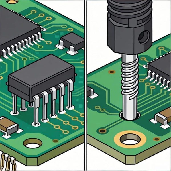
Through-Hole Connectors (THT)
Through-Hole connectors, also known as THT connectors, feature metal pins that extend through pre-drilled holes in the PCB. After inserting the pins through the holes, the opposite side of the PCB is soldered—either by hand or using wave soldering—to secure the connector in place.
This through-board design creates a mechanical anchor that is far more robust than surface-mount connections, making THT connectors well-suited for applications where stability and durability are paramount.
Traditional and widely used, THT connectors come in various forms, such as D-sub connectors, terminal blocks, power connectors, and pin headers. They are often preferred in applications that require high current carrying capacity, resistance to vibration, or easy manual assembly and repair.

SMT Connectors: Pros and Cons
SMT connectors have become the standard in many modern electronic devices, thanks to their compatibility with automated production and compact design. However, they also have limitations that make them unsuitable for certain applications. Below is a detailed breakdown of their key advantages and disadvantages.
Advantages of SMT Connectors
- Small Size & High Density: SMT connectors are significantly smaller than their Through-Hole counterparts, with a low profile and minimal footprint. This allows for high-density component placement on PCBs, making them ideal for compact, miniaturized electronic products such as smartphones, wearables, and IoT devices. Manufacturers can fit more components on a single PCB, reducing the overall size and weight of the end product.
- High-Speed Automated Production: SMT connectors are fully compatible with automated SMT placement machines and reflow soldering processes. This enables mass production at high speeds, reducing assembly time and labor costs. For B2B buyers sourcing components for large-volume production runs, this translates to faster time-to-market and lower per-unit costs.
- Superior High-Frequency Performance: The short pins of SMT connectors minimize signal path length, reducing signal interference (crosstalk) and signal loss. This makes them ideal for high-frequency applications, such as communication modules, laptops, and RF devices, where signal integrity is critical.
- Lower Mass-Production Costs: Compared to Through-Hole connectors, SMT connectors require less labor (no manual pin insertion) and eliminate the need for drilling holes in the PCB. The automated assembly process also reduces the risk of human error, further lowering production costs for large-scale orders.
- Flexible PCB Compatibility: SMT connectors can be mounted on both rigid and flexible PCBs (FPCs), making them versatile for a wide range of electronic products, including foldable devices and wearable technology.
Disadvantages of SMT Connectors
- Weak Mechanical Strength: Since SMT connectors are only soldered to the surface of the PCB, they have weaker mechanical stability compared to Through-Hole connectors. They are more susceptible to damage from vibration, shock, or physical stress, making them unsuitable for applications in harsh environments (e.g., industrial machinery, automotive under-hood systems).
- Limited High-Current Support: The small solder pads and short pins of SMT connectors have limited current-carrying capacity. They are not ideal for high-power applications, such as power supplies, industrial control systems, or automotive power modules, where large currents are required.
- Difficult Repairs & Rework: Repairing or reworking SMT connectors requires specialized equipment (e.g., hot air stations) and skilled technicians. Unlike Through-Hole connectors, which can be easily desoldered and replaced by hand, SMT connectors are prone to damage if not reworked carefully, increasing repair costs and downtime.
- Sensitivity to Soldering Quality: SMT connectors rely on precise reflow soldering to ensure a secure bond. Poor soldering (e.g., cold solder joints, solder bridges) can lead to intermittent connections or complete failure, requiring additional quality control measures during production.
- Limited Heat Dissipation: The surface-mount design provides less heat dissipation compared to Through-Hole connectors, which can transfer heat through their pins to the opposite side of the PCB. This can be a concern for high-temperature applications.
Typical Applications
SMT connectors are the preferred choice for applications that prioritize miniaturization, high-speed production, and high-frequency performance. Common use cases include:
Medical devices (portable monitors, diagnostic equipment)
Consumer electronics (smartphones, tablets, laptops, smart TVs)
Wearable devices (smartwatches, fitness trackers)
IoT devices (sensors, smart home devices, connected appliances)
Communication modules (5G devices, routers, modems)
What is SMT Assembly?
Through-Hole Connectors: Pros and Cons
Through-Hole connectors have been a staple in electronic manufacturing for decades, valued for their robustness and reliability. While they are less common in modern miniaturized devices, they remain indispensable for applications that require strength, high power, and easy maintenance. Below is a detailed overview of their advantages and disadvantages.
Advantages of Through-Hole Connectors
- Excellent Mechanical Stability: The pins of Through-Hole connectors pass through the PCB and are soldered on the opposite side, creating a secure mechanical anchor. This design provides superior resistance to vibration, shock, and physical stress, making them ideal for harsh environments such as industrial settings, automotive applications, and aerospace equipment.
- Superior High-Current & High-Power Support: Through-Hole connectors have larger pins and solder joints, which allow them to carry higher currents and handle more power than SMT connectors. They are commonly used in power supplies, industrial control systems, and automotive power modules, where reliable power delivery is critical.
- Easy Assembly & Repair: Through-Hole connectors can be easily inserted and soldered by hand, making them suitable for small-scale production runs or prototype assembly. They are also easy to desolder and replace, reducing repair time and costs—an important factor for B2B buyers looking to minimize downtime for their products.
- Stability in Harsh Environments: The through-board design and robust solder joints make Through-Hole connectors resistant to extreme temperatures, humidity, and chemical exposure. They are widely used in industrial control, automotive electronics, and outdoor equipment, where reliability in harsh conditions is non-negotiable.
- Proven Reliability: Through-Hole technology has been used for decades, with a well-established track record of reliability. For B2B buyers in industries such as medical, automotive, or aerospace, where product failure can have serious consequences, this proven reliability is a key advantage.
Disadvantages of Through-Hole Connectors
- Large Space Occupation: Through-Hole connectors require drilling holes in the PCB, which reduces the available space for other components. Their larger size and taller profile make them unsuitable for miniaturized devices, such as smartphones or wearables, where space is at a premium.
- Low Automation Efficiency: While Through-Hole connectors can be assembled using automated insertion machines, the process is slower and less efficient than SMT assembly. Manual insertion is often required for complex or low-volume production runs, increasing labor costs and production time.
- Poor High-Frequency Performance: The longer pins of Through-Hole connectors create longer signal paths, which can cause signal loss, crosstalk, and impedance mismatches. This makes them unsuitable for high-frequency applications, such as communication modules or RF devices.
- Higher Processing Costs: Drilling holes in the PCB adds an extra manufacturing step, increasing processing costs. Additionally, manual insertion and soldering (for small runs) or specialized automated equipment (for large runs) further drive up costs compared to SMT connectors.
- Limited PCB Density: The need for drilled holes and larger component size limits the number of Through-Hole connectors that can be placed on a single PCB, reducing overall layout density.
Typical Applications of Through-Hole Connectors
Through-Hole connectors are the preferred choice for applications that prioritize mechanical strength, high power, and easy maintenance. Common use cases include:
Aerospace and defense electronics
Industrial control systems (PLCs, sensors, motor drives)
Power supplies and power distribution equipment
Automotive electronics (engine control units, wiring harnesses)
Medical devices (imaging equipment, patient monitors)
Test and measurement equipment
Through-Hole Technology Overview
SMT vs Through-Hole Connectors: Full Comparison Table
| Feature | SMT Connectors | Through-Hole Connectors |
|---|---|---|
| Mechanical Strength | Low | High |
| Space Usage | High density | Low density |
| Production Speed | Very fast | Relatively slow |
| High Current Support | Limited | Excellent |
| High-Frequency Signal | Excellent | Average |
| Repair Difficulty | Difficult | Easy |
| Mass Production Cost | Lower | Higher |
| Best For | Miniature & high-speed devices | Industrial & high-stability devices |
How to Choose Between SMT and Through-Hole Connectors
FFor B2B buyers, engineers, and procurement teams, selecting the right connector type depends on a variety of factors—including product design, application requirements, production volume, and budget. Below is a step-by-step guide to help you make the optimal choice:
1. Evaluate Your Application Requirements
- Size & Miniaturization: If your product is compact (e.g., smartphone, wearable, IoT sensor), SMT connectors are the clear choice due to their small footprint and high density.
- Mechanical Stress & Environment: If your product will be exposed to vibration, shock, extreme temperatures, or harsh chemicals (e.g., industrial machinery, automotive under-hood systems), opt for Through-Hole connectors for their superior stability.
- Power & Current Needs: For high-power applications (e.g., power supplies, industrial control), Through-Hole connectors are better suited to handle large currents and heat.
- Signal Frequency: For high-frequency applications (e.g., 5G devices, RF modules), SMT connectors provide better signal integrity with shorter pins.
2. Consider Production Volume & Cost
- High-Volume Production: SMT connectors are ideal for large-scale production, as automated assembly reduces labor costs and increases speed.
- Low-Volume or Prototyping: Through-Hole connectors may be more cost-effective for small runs or prototypes, as they can be easily assembled by hand without specialized equipment.
3. Factor in Repair & Maintenance
If your product requires frequent maintenance or repair (e.g., industrial equipment, test instruments), Through-Hole connectors are easier to replace, reducing downtime and repair costs. For products with minimal maintenance needs (e.g., consumer electronics), SMT connectors are acceptable despite their repair challenges.
4. Consider Mixed Assembly
For complex products that require both high-speed signals and high power (e.g., automotive infotainment systems, industrial controllers), a mixed assembly approach is often optimal. Use SMT connectors for signal components (e.g., data connectors) and Through-Hole connectors for power components (e.g., power terminals), combining the strengths of both technologies.
Conclusion
SMT and Through-Hole connectors each have unique strengths and limitations, and the right choice depends on your specific application, production needs, and budget. SMT connectors excel in miniaturization, high-speed production, and high-frequency performance—making them ideal for consumer electronics and IoT devices. Through-Hole connectors, on the other hand, offer superior mechanical stability, high-power support, and easy repair—making them indispensable for industrial, automotive, and high-reliability applications.
As a reliable B2B electronic components supplier , we offer a full range of SMT and Through-Hole connectors from top manufacturers, including pin headers, board-to-board connectors, terminal blocks, and power connectors. We provide samples for testing, bulk ordering options, and technical support to help you select the right components for your project. Whether you’re sourcing for high-volume production or custom prototypes, our team is here to support your procurement needs.


