
Best USB C 16 Pin DIP Vertical Connector | 5A Through-Hole Type-C Female H=6.5mm | USB-TC16-F09
USB C 16 Pin DIP Vertical Connector — Reliable Through-Hole PCB Mount Type-C Female
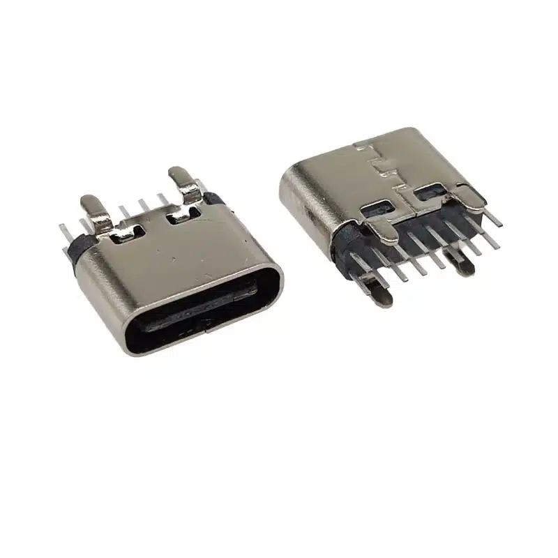
The USB-TC16-F09 is a USB C 16 pin DIP vertical connector (Type-C female receptacle) engineered for through-hole PCB mounting in a vertical (upright) orientation. Manufactured by Vistar Electronics, this connector delivers dependable USB 2.0 charging and data connectivity with superior mechanical anchoring — making it the preferred choice for consumer electronics, industrial control systems, and smart devices where the USB-C port is subject to repeated plug-and-unplug stress.
Unlike SMT (surface-mount) connectors that rely solely on solder paste joints on the PCB surface, the USB C 16 pin DIP vertical connector drives its pins through plated through-holes in the PCB board, soldering on both the top and bottom side. This through-hole (DIP) anchoring method provides significantly greater pull-out force resistance and side-load strength — critical for ports that experience mechanical stress from cable strain, user handling, and high-cycle mating over the product’s service life.
The USB-TC16-F09 features a 16-pin USB-C configuration, retaining the essential signal and power pins of the full USB-C specification: VBUS, GND, D+, D−, CC1, and CC2. The CC1 and CC2 configuration channel pins enable USB Power Delivery protocol negotiation, allowing the connector to support up to 5A fast charging when paired with a compatible USB PD controller IC on the host PCB. Data transmission operates at USB 2.0 speeds (up to 480 Mbps), making this connector cost-effective for charging-primary and low-speed data applications where USB 3.x SuperSpeed is not required.
The connector is available in two height variants — H=6.5mm and H=6.8mm above the PCB surface — sharing an identical PCB footprint (pin pitch and hole pattern), allowing engineers to substitute between variants in the same layout without gerber modifications. Operating temperature range is −25°C to +85°C, suitable for both consumer and light-industrial environments. The LCP insulator body withstands wave soldering temperatures, and the stainless steel shell provides EMI shielding and structural rigidity.
According to the USB-IF Type-C Specification Revision 2.0, the 16-pin USB-C receptacle is a recognised subset configuration that fully complies with the USB-C mechanical and electrical interface standard. All standard USB-C cables and plugs mate correctly with the USB-TC16-F09, including reversible insertion in both orientations.
The USB-TC16-F09 is manufactured in Vistar Electronics’ ISO 9001:2015 certified facility in Pingshan District, Shenzhen, China, and is fully compliant with RoHS 3 (EU Directive 2015/863) and REACH SVHC regulations. Tray and reel packaging are available for production assembly. For the SMT right-angle alternative, see our USB-C 16 pin SMT right-angle connector, or browse the full USB-C connector range.
## Specifications
USB-TC16-F09 Technical Specifications — USB C 16 Pin DIP Vertical Connector
| Parameter | Value | Notes |
|---|---|---|
| Part Number | USB-TC16-F09 | Standard catalog item |
| Connector Type | USB-C Female Receptacle | Type-C female, 16-pin |
| USB Standard | USB 2.0 Type-C | 480 Mbps data + 5A charging |
| Pin Count | 16 Pins | VBUS, GND, D+, D−, CC1, CC2 + shell |
| Mount Type | DIP Through-Hole | Wave or hand soldering |
| Orientation | Vertical / 90° upright | Port opening faces upward |
| Height (H) | H = 6.5mm / H = 6.8mm | Two variants, same footprint |
| Current Rating | 5A (VBUS) | USB PD compatible |
| Voltage Rating | 30V DC Max | — |
| Insertion Force | ≤ 20N | Max per IEC 62680 |
| Withdrawal Force | 5 – 20N | — |
| Mating Cycles | 10,000 cycles | High durability |
| Contact Material | Copper Alloy, Gold Plated | Low contact resistance |
| Insulator | LCP (High-Temp) | Wave-solder compatible |
| Shell Material | Stainless Steel | EMI shielding + mechanical rigidity |
| Operating Temp. | −25°C to +85°C | Consumer & light-industrial |
| Storage Temp. | −40°C to +125°C | — |
| Packaging | Tray / Reel | Production ready |
| Compliance | RoHS 3, REACH SVHC | EU & global export ready |
| Certification | ISO 9001:2015 | Factory quality management |
6 Proven Advantages of the USB C 16 Pin DIP Vertical Through-Hole Connector
DIP Through-Hole — 10× Stronger Mechanical Anchoring
Through-hole pins penetrate the PCB and are soldered on both sides, creating a mechanical bond that withstands far greater pull-out force and cable side-load than any surface-mount connector. Ideal for ports subject to repeated plug/unplug stress, accidental cable strain, and end-user handling in consumer and industrial products.
Vertical Upright Orientation — Upward-Facing Port Design
The 90° vertical mounting positions the USB-C opening directly upward from the PCB surface, enabling top-panel charging ports, desk-facing USB-C sockets on desktop hubs, and front-panel device interfaces. No horizontal routing of cables across the board surface is required, simplifying PCB layout and cable management.
5A USB Power Delivery Ready — Up to 100W Charging
Rated at 5A / 30VDC with CC1 and CC2 configuration channel pins for USB PD negotiation. Supports USB PD 3.1 up to 100W (5A × 20V) when paired with a compatible USB PD controller IC (e.g. FUSB302, CYPD, or equivalent). Hardware-ready for fast-charging applications without additional connector changes.
Two Height Options — H=6.5mm & H=6.8mm, Same Footprint
Available in two height variants to accommodate different chassis clearance requirements. Both H=6.5mm and H=6.8mm variants share an identical PCB footprint — identical pin pitch, hole diameter, and pad layout — allowing BOM substitution and PCB reuse without any layout modifications.
10,000 Mating Cycles — High-Durability USB-C Interface
Rated for 10,000 insertion and withdrawal cycles, exceeding the standard commercial grade requirement. Gold-plated copper alloy contacts maintain stable contact resistance throughout the connector’s life. The reversible USB-C plug interface eliminates incorrect insertion, reducing connector damage from misaligned mating.
RoHS 3 & REACH Compliant — Safe for Global Export
Fully compliant with RoHS 3 (EU Directive 2015/863) restricting 10 hazardous substances, and REACH SVHC substance regulations. Compliance declarations and test documentation are available on request for EU CE marking, supply chain qualification, and customer audit programs.
Where to Use the USB C 16 Pin DIP Vertical Connector — Top Use Cases
USB C 16 Pin DIP Vertical Connector — Frequently Asked Questions
What is a USB C 16 pin DIP vertical connector and how does it differ from SMT?
A USB C 16 pin DIP vertical connector uses through-hole (DIP) mounting: its pins pass through drilled holes in the PCB and are soldered on the back side, anchoring the connector mechanically from both sides of the board. An SMT connector solders only to surface pads on the top layer.
The key advantage of DIP through-hole mounting is dramatically stronger mechanical pull-out resistance — typically 5–10× greater than SMT mounting. This matters for USB-C ports that experience regular cable strain, user-applied side loads, or frequent mating cycles. The trade-off is that through-hole assembly requires drilled holes in the PCB and is not compatible with fully automated SMT reflow lines — wave soldering or manual soldering is required for the through-hole pins.
What USB standard does the USB-TC16-F09 support? Does it support USB 3.1?
The USB-TC16-F09 supports USB 2.0 data (up to 480 Mbps) and 5A power delivery via the CC1/CC2 pins. The 16-pin USB-C configuration retains the essential USB 2.0 signal pairs (D+/D−), power (VBUS/GND), and configuration channel pins (CC1/CC2), but omits the SuperSpeed TX/RX differential pairs present in the full 24-pin USB-C connector.
For applications requiring USB 3.1 Gen 2 (10 Gbps) SuperSpeed data transmission, consider our 24-pin USB-C mid-mount connector (USB-TC24-M04) which carries the complete USB-C pin assignment. The 16-pin variant is the cost-optimized choice for charging-primary and USB 2.0 data applications.
Can the USB-TC16-F09 support USB Power Delivery (PD) fast charging?
Yes. The USB-TC16-F09 includes the CC1 and CC2 configuration channel pins required for USB Power Delivery protocol negotiation, and is rated at 5A / 30VDC — meeting the hardware requirements for USB PD. With a compatible USB PD controller IC on the host PCB (such as FUSB302, CYPD3177, or similar), the connector can support USB PD 3.0 up to 100W (5A × 20V).
The connector itself is a passive component; the USB PD controller IC on your PCB is responsible for negotiating the charging voltage and current with the attached cable and power adapter. See the USB-IF USB PD specification for implementation guidance.
What are the two height variants H=6.5mm and H=6.8mm — which should I choose?
Both variants have the same PCB footprint (identical hole pattern and pad layout), differing only in the distance from the PCB surface to the top of the connector body: 6.5mm or 6.8mm. Choose based on your chassis design:
- H=6.5mm — for designs with tight PCB-to-panel clearance, where minimizing connector height is a priority.
- H=6.8mm — where slightly more height above the PCB is acceptable, or where the panel cutout alignment benefits from the additional 0.3mm.
Since both variants use the same PCB footprint, you can specify either in your BOM without requiring PCB layout changes. If in doubt, order free samples of both variants to confirm fitment before production.
Is the USB-TC16-F09 compatible with standard USB-C cables?
Yes. The USB-TC16-F09 is mechanically compliant with the USB-IF Type-C Connector Specification and mates correctly with all standard USB-C plug cables, including USB 2.0, USB 3.1, and USB PD cables. The reversible USB-C plug interface means the cable can be inserted in either orientation without risk of incorrect mating. The connector supports cables rated up to 5A for full USB PD charging capability.
What assembly process is recommended for the USB-TC16-F09?
The USB-TC16-F09 is compatible with two assembly methods:
- Wave soldering — the most common method for through-hole PCB assembly. Insert the connector into the PCB holes and pass through a wave solder machine. The LCP insulator body and stainless steel shell are rated to withstand wave soldering temperatures.
- Manual soldering — suitable for prototyping, low-volume production, and repair. Hand-solder each pin using a soldering iron at appropriate temperature.
The connector is available in tray packaging for both methods. Reel packaging is also available for automated through-hole insertion machines used in higher-volume production environments.
What is the MOQ and can I get a free sample?
Standard MOQ is 1,000 pieces with a 2–4 week production lead time for standard configurations. Free samples (both H=6.5mm and H=6.8mm variants) are available for qualified engineering and product development projects. Contact sales@vistarelectronics.com with your company details, project application, and required height variant, or click the “Get a Quote” button on this page.

6 Pin USB C Connector Middle Mount – Compact SMT Receptacle for Modern Electronics

USB Type C Surface Mount Connector 16P — USB-TC16-F04 16 Pin SMD Horizontal Receptacle with 5A Rating

PCB mount Connector USB Type C female 24 pin SMT horizontal CL=1.57 L=9.17

USB Type-C Connector 24 Pin Flank SMT — High-Speed USB 3.2 Type-C Female Receptacle

16 Pin USB-C Connector Mid-Mount SMT – 10Gbps USB 3.2 Receptacle
USB Motherboard Connector C 16P SMT Right Angle USB 3.1 Female Receptacle

USB 3.1 Type-C Connector 24 Pin SMT Female Receptacle

24 Pin USB Type-C Female Connector for USB 3.1 High-Speed & Fast Charging Applications

Waterproof USB-C Connector Guide: Usage, Maintenance & Common Mistakes
Complete waterproof USB-C connector guide covering IP67/IP68 differences, installation, maintenance, common mistakes, and testing. Ensure long-term reliability outdoors. A fleet operator once...

USB-C Connector Pinout Explained: Complete 24-Pin, 16-Pin, 12-Pin & 6-Pin Guide for Engineers (2026)
The Procurement Nightmare Every Engineer Knows USB-C Connector Pinout Explained: Complete 24-Pin, 16-Pin, 12-Pin & 6-Pin Guide for Engineers (2026) You have...

USB-C PCB Layout Design Guide for High-Speed PCB Applications
Master USB-C PCB layout with 12 essential design rules covering differential pair routing, impedance control, power delivery, and ESD protection. Practical engineering...