

Mid Mount USB C Connector — 24 Pin Double Shell, L=8.65mm, CL=0.32mm for Ultra-Thin PCBs
The USB-TC24-F11 is a mid mount usb c connector built around a double-shell body, L=8.65mm length, and CL=0.32mm board recess. It is a 24-pin full-featured receptacle, rated 5A / 30V DC, 10,000 mating cycles, and −40°C to +85°C, with SMT mounting and a mid-mount footprint that places the connector body partly inside a PCB cutout. The double-shell structure is the point of this page. For the single-shell mid-mount variant, see the USB-TC24-F10 mid-mount page.
24 Pin Mid Mount USB C Connector — What the Double-Shell Structure Changes
A 24 pin mid mount usb c connector places the mating opening partly inside a PCB cutout instead of sitting entirely above the board. On the F11, the body length is L=8.65mm and the recess depth is CL=0.32mm. This lower above-board profile matters when the enclosure is thin and the USB-C port sits close to the PCB surface. The mid-mount footprint is the mechanical feature; the double-shell body is the second distinguishing point.
The F11 uses two shell layers around the connector body, while the F10 is the single-shell mid-mount variant. The double shell affects the connector envelope, EMI shielding around the mating interface, and how the port fits a panel cutout. These two pages exist because the shell count is not a cosmetic difference. If the design calls for the single-shell envelope, the F10 page is the correct starting point. If the requirement is the double-shell mid-mount body with L=8.65mm and CL=0.32mm, this page applies.
On the electrical side, the F11 keeps the full 24-pin contact set: four VBUS pins, four GND pins, D+/D−, SuperSpeed TX/RX pairs, CC1/CC2, and SBU1/SBU2. That contact set is what separates a full-featured 24-pin receptacle from a 16-pin or 6-pin USB-C port. The mid-mount recess and the double shell change the mechanical envelope, not the contact assignment. Data rate and power delivery still depend on the host controller, device PHY, cable, and PD circuit on the same board.
The F11 sits in the USB-C receptacle product family alongside top-mount SMT, DIP+SMT hybrid, single-row SMT, and single-shell mid-mount models. It is not a replacement for those pages. It is the double-shell mid-mount 24-pin option for designs where the board height is constrained and the enclosure needs the port recessed into the PCB.
USB C Receptacle Mid Mount PCB — Technical Specifications for USB-TC24-F11
| Parameter | Specification | Notes |
|---|---|---|
| Part Number | USB-TC24-F11 | Double-shell mid-mount variant |
| Connector Type | USB Type-C Female Receptacle | 24-pin full-featured |
| Pin Count | 24 Pins | A-side / B-side dual row |
| Mounting Type | SMT, Mid-Mount | Body partly recessed into PCB cutout |
| Shell | Double Shell | F10 is the single-shell mid-mount variant |
| Length L | 8.65 mm | Body length |
| CL (Board Recess) | 0.32 mm | Mid-mount recess depth |
| Current Rating | 5A Max | Connector-level VBUS/GND rating |
| Voltage Rating | 30V DC | Connector-level rating |
| Durability | 10,000 Mating Cycles | Insertion / withdrawal |
| Operating Temperature | −40°C to +85°C | — |
| Contact Material | Copper Alloy | — |
| Contact Plating | Gold Plated | — |
| Housing Material | High Temperature Thermoplastic | Lead-free reflow compatible |
| Compliance | RoHS / REACH | — |
| Packaging | Reel / Tray | Production handling options |
The L and CL values are the two dimensions that separate this mid-mount layout from a top-mount layout. L=8.65mm defines the body length; CL=0.32mm defines how far the connector sits into the board. Both should be taken from the current F11 drawing before the PCB cutout and keep-out are released. The 5A / 30V DC figure is a connector-level rating, not the delivered power of a finished product. USB PD wattage still depends on the PD controller, power supply, cable, thermal path, and protection circuit. For the official Type-C interface rules behind the 24-pin contact set, the USB-IF USB Type-C specification page documents the interface dimensions and pin functions.
Double Shell Mid Mount USB C Receptacle — Key Design Features
Mid-Mount with CL=0.32mm Recess
The connector body sits partly in a PCB cutout, with CL=0.32mm defining the recess depth. This lowers the above-board profile compared with a standard top-mount 24-pin SMT receptacle, which matters in thin enclosures where the port height is constrained.
Double-Shell Envelope, L=8.65mm Body
The F11 uses a double-shell body with L=8.65mm length. The F10 is the single-shell mid-mount variant. The shell count affects the connector envelope, EMI shielding around the mating interface, and the way the port fits the enclosure cutout. The two should be compared on the drawing, not treated as interchangeable.
Full 24-Pin Contact Set
The receptacle carries VBUS, GND, D+/D−, SuperSpeed TX/RX pairs, CC1/CC2, and SBU1/SBU2. This is the contact set that a 16-pin or 6-pin USB-C port does not have, and it is what allows the connector to support USB 3.2 Gen 2 signaling and alternate modes when the host, device, and cable support them.
5A / 30V DC Connector Rating
The VBUS/GND contacts are rated for 5A at 30V DC at the connector level. This is the connector ceiling, not the delivered wattage of a finished product. Actual USB PD power depends on the PD controller, power supply, cable, thermal path, and protection circuit on the same board.
10,000 Mating Cycles
Rated for 10,000 insertion and withdrawal cycles at the connector level. Product-level cycle life still depends on enclosure alignment, cable handling, and how the panel supports the mated plug. The mid-mount recess and the double-shell body both affect that mechanical interface.
SMT Reflow, Mid-Mount Cutout
The connector is SMT-mounted, so the signal pads and shell anchor pads are reflowed with the top-side components. The mid-mount footprint adds a PCB cutout requirement. The board house should confirm the cutout dimensions against the F11 drawing before the board is released.
Mid Mount USB C Connector L=8.65mm — Where the Double-Shell Mid-Mount Fits
A mid mount usb c connector l=8.65mm recess is useful when the product enclosure is thin and the USB-C port cannot sit fully above the PCB. The mid-mount structure lets the connector body drop into a board cutout, so the mating opening lines up with a lower panel opening. The double-shell body adds a second shell layer around the mating interface, which is the reason to choose F11 over the single-shell F10 when the design calls for that envelope.
Mid-mount is not a universal upgrade. It adds a PCB cutout requirement and changes the mechanical load path compared with a top-mount receptacle. If the enclosure is not height-constrained, a top-mount or DIP+SMT receptacle is often simpler to assemble. The F11 is intended for designs where the mid-mount recess solves an actual mechanical constraint and the double-shell envelope is part of the requirement, not as a default choice across every 24-pin project.
24 Pin USB-C Pinout — Signal Groups Inside the Double-Shell Mid-Mount Receptacle
The 24-pin Type-C interface uses a symmetrical dual-row layout so the plug works in either orientation. The mid-mount recess and the double-shell body do not change the contact map; they change the mechanical envelope. The table below groups the 24 contacts by function.
| Function Group | Role | Notes |
|---|---|---|
| VBUS (×4) | Power delivery | Connector rated 5A at VBUS/GND |
| GND (×4) | Ground return | Paired with VBUS for current path |
| D+ / D− (×2 pairs) | USB 2.0 data | Mirrored on A and B sides |
| SSTX1/2, SSRX1/2 (×4 pairs) | SuperSpeed differential | USB 3.2 Gen 2 signaling; dual-lane capable |
| CC1 / CC2 | Configuration channel | Orientation detection and PD negotiation |
| SBU1 / SBU2 | Sideband use | Alternate mode, e.g. DisplayPort Alt Mode |
The exact pin numbering for the A-side and B-side rows should be taken from the current drawing before PCB layout. For a full pin-by-pin table across USB-C receptacle types, the USB-C connector pinout guide includes the 24-pin front-view assignment and a comparison with 16-pin and 6-pin variants. The pin map is the same for the F11 double-shell mid-mount and the F10 single-shell mid-mount; the mounting and shell structure sit outside the contact assignment.
F11 vs F10 and Other 24-Pin USB-C Receptacles — Selection Guide
The 24-pin lineup has several variants that share the same contact set but differ in mounting, shell, and assembly process. The table below is a selection guide, not a ranking. The F11 and F10 are both mid-mount 24-pin receptacles with L=8.65mm and CL=0.32mm, but they are not the same connector: F11 is the double-shell variant, F10 is the single-shell variant. The shell envelope should be compared on the drawings before either part is designed in.
| Requirement | Start With | Why |
|---|---|---|
| Double-shell mid-mount, L=8.65mm, CL=0.32mm | USB-TC24-F11 (this page) | Double-shell body; mid-mount recess for thin enclosures |
| Single-shell mid-mount, L=8.65mm, CL=0.32mm | USB-TC24-F10 | Single-shell envelope; compare drawing before selection |
| Standard top-mount SMT, no PCB cutout | USB-TC24-F04 | Pure SMT top-mount; simpler assembly, taller above-board profile |
| DIP+SMT hybrid shell anchoring | USB-TC24-F09 | Through-hole shell legs for high-insertion or vibration-prone designs |
| Single-row SMT, USB4 40Gbps positioning | USB-TC24-F30 | Single-row right-angle SMT; different footprint and speed positioning |
| Waterproof IP67/IP68 mid-mount | USB-TC24-FW10 | Sealed mid-mount for outdoor or wet environments |
Among mid mount usb c connector options, the F11 should be selected on the shell envelope and the L/CL dimensions, not on the pin count alone. The 24-pin contact set is shared across these variants. If the design does not actually need a mid-mount cutout, a top-mount SMT or DIP+SMT receptacle is often easier to assemble. If the design needs a mid-mount but the envelope is different, the F10 or another mid-mount variant in the USB-C receptacle category should be compared before the PCB cutout is finalized.
PCB Cutout and SMT Assembly Notes for the Double-Shell Mid-Mount
A mid-mount connector requires a PCB cutout so the body can sit partly below the board surface. The cutout dimensions, the SMT land pattern, and the connector body keep-out should all be checked against the current F11 drawing. The locating features on the connector body should align with the cutout during placement, and the SMT pads should reflow with the rest of the top-side components.
For the SuperSpeed pairs, route the differential pairs according to the board stack-up and the controller requirements. For VBUS and GND, size the copper for the intended current with thermal margin; the 5A connector rating is not a substitute for adequate copper area. If the design uses the CC pins for PD negotiation, follow the USB-C controller’s routing guidance. The mid-mount recess does not change the signal routing rules; it changes where the connector body sits relative to the board.
Before release, confirm the cutout tolerance and the connector coplanarity against the F11 drawing. A mid-mount part with a PCB cutout has less room for placement error than a top-mount part, so the assembly house should review the cutout and the paste deposit on the anchor pads. If the line cannot handle a PCB cutout, a top-mount SMT receptacle is the simpler alternative.
FAQ — USB-TC24-F11 Double-Shell Mid-Mount Receptacle
Is the F11 the same as the F10 mid-mount receptacle?
No. Both are mid-mount 24-pin receptacles with L=8.65mm and CL=0.32mm, but the F11 is the double-shell variant and the F10 is the single-shell variant. The shell count and the resulting connector envelope are different. Compare the drawings before choosing, and do not treat the two as interchangeable.
What do L=8.65mm and CL=0.32mm mean on this connector?
L=8.65mm is the connector body length. CL=0.32mm is the board recess depth that defines how far the mid-mount body sits into the PCB cutout. Both are mechanical dimensions that should be taken from the current F11 drawing before the board keep-out is released.
Does the double shell change the pinout or the data rate?
No. The 24-pin contact set and its functional pin groups are the same as a single-shell mid-mount or top-mount 24-pin receptacle. The double shell changes the mechanical envelope and the EMI shielding around the mating interface, not the contact assignment or the negotiated data rate. Data rate is set by the host, device, and cable.
Does the 5A rating mean the product supports 100W USB PD?
No. The 5A rating is the connector’s VBUS/GND rating. 100W USB PD (20V/5A) is a system-level result that requires a compatible PD controller, power supply, cable, thermal design, and protection circuit. The connector is one element of that design, not a guarantee of delivered wattage.
What PCB change is required for this mid-mount connector?
A mid-mount connector requires a slot or cutout in the PCB so the connector body can sit partly below the board surface. The cutout dimensions, the SMT land pattern, and the connector body keep-out should all be checked against the F11 drawing. If the board cannot accommodate a cutout, a top-mount SMT receptacle is the simpler alternative.
Is the F11 available in a single-shell version?
The F11 is the double-shell mid-mount variant. The single-shell mid-mount 24-pin option is covered on the USB-TC24-F10 page. Shell count affects the connector envelope and the enclosure fit, so the two should be compared on the drawing before selection.

USB Type C connector on motherboard 14 pin

USB 3.2 Gen 2 Type-C Connector – 24 Pin 10Gbps SMT

24 Pin Vertical USB-C Connector SMT (USB-TC24-F12)
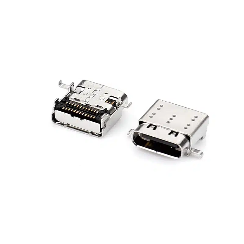
USB C Connector SMT 24 Pin — Right-Angle USB-C Receptacle, CL=1.57mm L=9.17mm, USB-TC24-F22
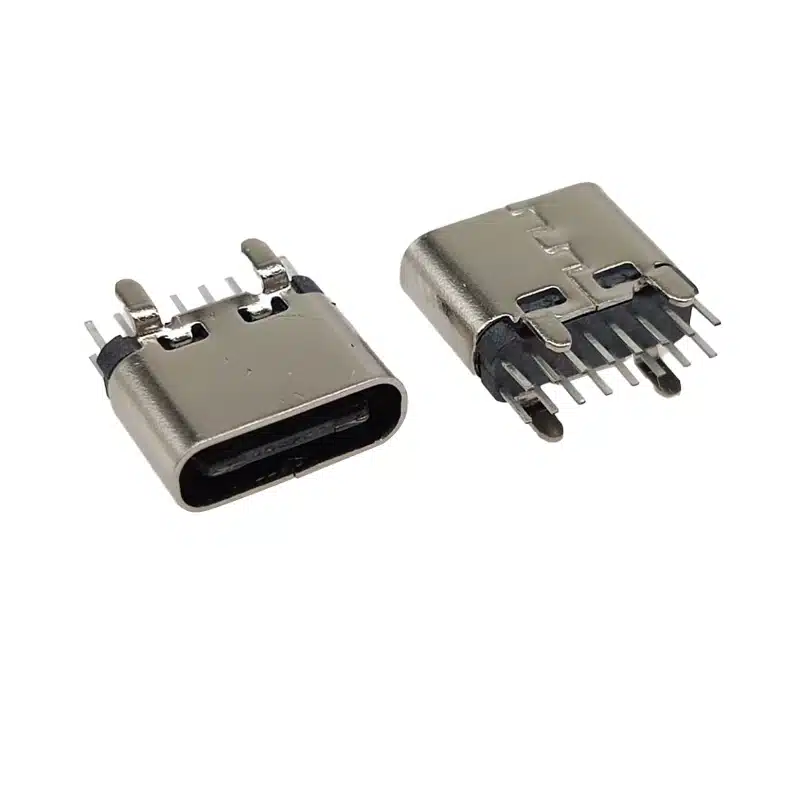
Best USB C 16 Pin DIP Vertical Connector | 3A Through-Hole Type-C Female H=6.5mm | USB-TC16-F09

24 Pin Vertical USB C Connector for SMT PCB Mounting
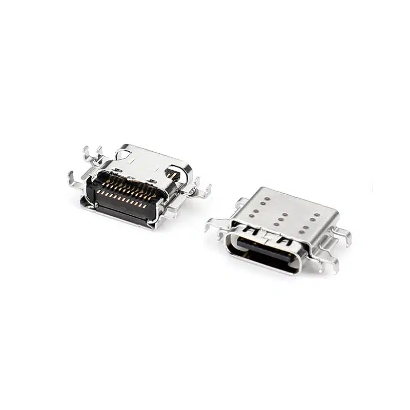
24 Pin USB-C Connector Female SMT (USB-TC24-F25)

24 Pin USB Type-C Female Connector Mid-Mount — Single Shell, L=8.65mm, CL=0.32mm for Ultra-Thin PCBs

USB-C Connector Pinout Guide for Engineers: 24-Pin vs 16-Pin Signal Assignment & PCB Routing
When moving from the pinout to a physical part, orientation matters as much as pin count. The USB-TC24-F12 (vertical SMT solder mount)...

USB-C 24-Pin Full-Featured vs. 16-Pin USB 2.0: Key PCB Layout Considerations
Understanding the differences in PCB layout between the USB-C 24-pin full-featured and 16-pin USB 2.0 connectors is crucial for ensuring stable device...
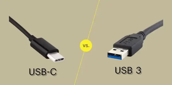
USB-C vs USB 3.0 vs USB4: Which Connector Do You Need for Your Next Design?
If you’re specifying a USB connector for a new product, you’ve probably run into three overlapping terms: USB-C, USB 3.0, and USB4....