

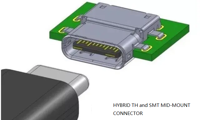
USB4 Female Type c USB connector 24 Pin mid-mount SMT CL=0.5mm L=8.17mm
USB4 Type-C Connector with Mid-Mount Design — Solving the Thickness Challenge
As electronic devices continue to shrink in thickness, the traditional top-mounted USB-C 24 Pin Mid-Mount Connector — which typically sits 2–3 mm above the PCB — becomes a design bottleneck. The mid-mount configuration directly addresses this by recessing the connector body into a precision-routed slot at the PCB edge, reducing the height above board to as low as 0.5 mm. This is a game‑changer for industrial designers who want to maintain full USB4 functionality without sacrificing sleek product enclosures.
The USB4 Type-C connector market is expanding rapidly, driven by the demand for faster data, higher power, and thinner form factors. This mid-mount receptacle is fully compatible with USB4 Gen 3 and Gen 4 specifications, supporting dual-lane operation at 20 Gbps per lane. It also retains backward compatibility with USB 3.2, USB 2.0, and DisplayPort Alt Mode, making it a versatile choice for a wide range of applications — from consumer ultrabooks to industrial panel PCs.
Unlike vertical or right‑angle variants, the mid‑mount orientation allows the connector to be positioned at the very edge of the board, minimizing the PCB real estate required for the port. This is particularly valuable in space‑constrained designs like tablet motherboards or mini‑PCs where every square millimeter counts.
USB Type‑C 24 Pin Receptacle — Full Technical Specifications
| Parameter | Specification | Notes |
|---|---|---|
| Part Number | USB-TC24-M20 | Standard catalog |
| Connector Type | USB Type-C Female Receptacle | 24‑pin full‑featured |
| Interface Standard | USB4 / USB 3.2 Gen 2×2 | 40 Gbps capable |
| Pin Count | 24 | All SuperSpeed, USB2, CC, SBU, VBUS |
| Mounting Style | Mid-Mount SMT | PCB edge slot required |
| Orientation | Horizontal (side‑entry) | Parallel to board plane |
| Height Above PCB | 0.5 mm (typical) | ±0.1 mm tolerance |
| Current Rating | 5 A (VBUS) | USB PD up to 100 W |
| Voltage Rating | 30 V DC | — |
| Contact Material | Copper Alloy | Gold‑plated (0.3 µm) |
| Housing Material | LCP (High‑Temperature) | UL94 V‑0 |
| Shell Material | Stainless Steel | EMI shielding |
| Mating Cycles | 10,000 | Durability testing |
| Operating Temperature | −40°C to +85°C | Industrial grade |
| Packaging | Tape & Reel (500 pcs) | Automated SMT ready |
| Compliance | RoHS 3, REACH, USB‑IF (design) | — |
Mid‑Mount USB‑C Connector: Five Engineering Advantages That Make a Difference
0.5 mm Ultra‑Low Profile
The mid‑mount design drops the connector into a PCB slot, achieving the industry’s lowest height above board. This enables thinner product enclosures without compromising port robustness.
USB4 & 40 Gbps Ready
Full 24‑pin configuration supports dual‑lane SuperSpeed operation, meeting the stringent signal integrity requirements for USB4 Gen 3 (20 Gbps per lane) and Thunderbolt 3/4 Alt Mode.
5 A Power Delivery
With a 5 A current rating, the connector supports USB PD up to 100 W (20 V, 5 A) — more than enough for charging laptops, monitors, and high‑power peripherals.
10,000 Mating Cycles
Built with a robust stainless steel shell and gold‑plated contacts, this receptacle withstands daily plug‑and‑unplug scenarios over the product’s entire lifecycle.
SMT Reflow Compatible
The tape‑and‑reel packaging and high‑temperature LCP housing make it compatible with standard SMT reflow processes, ensuring high assembly yield and low manufacturing cost.
Excellent EMI Shielding
The stainless steel shell provides effective electromagnetic interference shielding, crucial for preserving signal integrity in high‑speed digital designs.
Where the USB‑C SMT Connector Excels — Real‑World Applications
Enables the sleekest designs with full USB4 port functionality, including video output and 100 W charging.
Thin‑form‑factor tablets benefit from the 0.5 mm profile while maintaining high‑speed data and charging.
Multiple mid‑mount ports can be stacked on edge‑mounted PCBs for compact multi‑port accessories.
Robust mating cycles and wide temperature range suit factory automation and HMI applications.
Space‑constrained small‑form‑factor PCs require low‑profile connectors to maximise internal volume.
Reliable, durable connectors for portable diagnostic equipment and patient monitors.
USB‑C 24 Pin Mid‑Mount Connector — Frequently Asked Questions
What is the difference between mid‑mount and top‑mount USB‑C connectors?
Mid‑mount connectors sit partially inside a routed slot in the PCB, reducing the height above board to 0.5 mm. Top‑mount connectors sit entirely on top of the PCB, adding 2–3 mm of height. Mid‑mount is preferred for ultra‑thin devices; top‑mount is simpler to implement and does not require PCB cutouts.
Does this connector support USB4 at 40 Gbps?
Yes, the 24‑pin mid‑mount receptacle is designed to support USB4 Gen 3 at 20 Gbps per lane (total 40 Gbps) when paired with a compatible controller and proper PCB layout. Actual data rates depend on the overall system design.
What PCB thickness is recommended for this mid‑mount connector?
The connector is optimized for standard PCB thicknesses of 1.0 mm to 1.6 mm. The mechanical drawing specifies the exact slot dimensions; we recommend ordering samples to validate fit on your specific board thickness.
Can I get free samples for testing?
Yes, free engineering samples are available for qualified projects. Contact our sales team at sales@vistarelectronics.com with your company and project details, and we will arrange samples promptly.
What is the MOQ and lead time?
Standard MOQ is 1,000 pieces with a lead time of 2–4 weeks for standard configurations. Custom options (plating, shell finish, etc.) may have longer lead times.
USB‑C Connector Category
USB‑C PCB Layout Guide
Selection Guide
Signal Integrity Deep‑Dive
📄 USB‑IF Type‑C Specification (Official)

USB C Connector Pinout 24 Pin DIP+SMT — Full USB 3.1 Type-C Female Receptacle

Vertical USB-C Connector 24 Pin SMT Straight – High-Reliability Type-C Receptacle for PCB

USB Type-C Female Connector 6 Pin Mid-Mount – Durable 3A Power Delivery for Space‑Limited PCBs

Surface mount USB C connector smt 24pin right angle CL=1.57mm L=9.17

USB 3.1 Gen 2 Type-C Motherboard Connector 24pin

USB-C Female connector 24pin SMT Vertical

USB Type C Surface Mount Connector 16P — USB-TC16-F04 16 Pin SMD Horizontal Receptacle with 5A Rating

USB C Connector female 24 pin top mount right angle
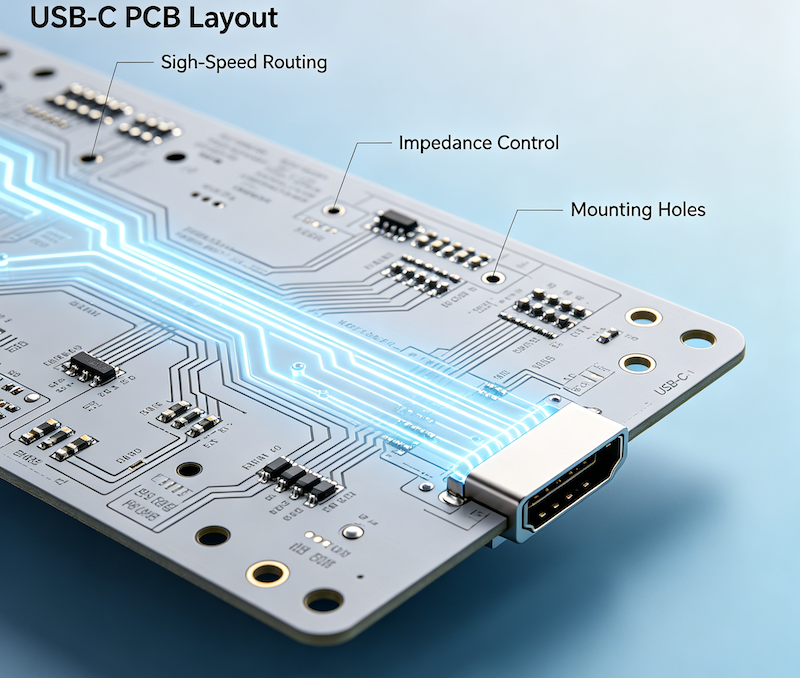
USB-C PCB Layout Design Guide for High-Speed PCB Applications
Master USB-C PCB layout with 12 essential design rules covering differential pair routing, impedance control, power delivery, and ESD protection. Practical engineering...

USB-C Connector Types Explained: A Complete Guide for Engineers and Buyers
If you’re a hardware engineer or sourcing professional selecting USB-C connectors for your next PCB design, understanding the different USB-C connector types...
The Ultimate USB-C Mid Mount Connector Design Guide: 8 Engineering Tips for Ultra-Thin Devices
Learn how to select the right USB-C mid mount connector for ultra-thin devices. Compare mounting styles, PCB layout requirements, power delivery, and...