
USB-C 16 Pin SMT On-Board Connector for USB Power Delivery & Compact High-Density PCB Design
USB-C 16 Pin SMT On-Board Connector Overview
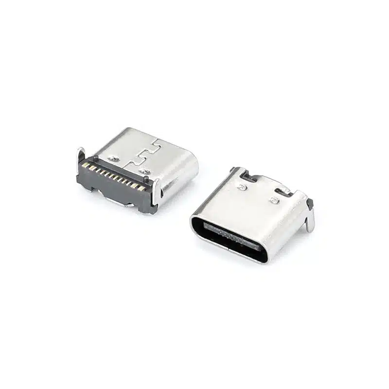
The USB-C 16 pin connector is a compact USB Type‑C female receptacle designed for applications that require reliable power delivery and basic data communication without the need for full SuperSpeed USB 3.x lanes. This connector is widely used in space‑constrained electronic designs where stable charging, USB 2.0 data transmission, and compact PCB integration are required.
Compared with full 24‑pin USB‑C connectors, the 16‑pin architecture reduces complexity while still maintaining essential USB‑C functions such as USB Power Delivery (PD), CC communication channels, D+/D‑ data lines, and VBUS/GND power delivery. This makes it an ideal solution for cost‑sensitive and power‑focused applications.
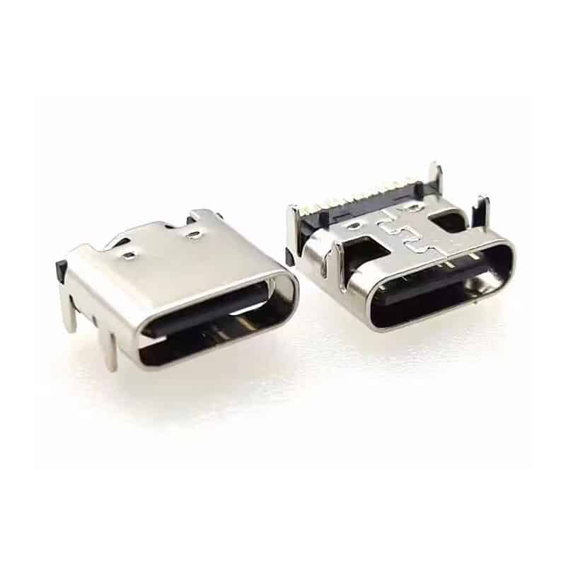
The on‑board SMT design ensures efficient automated PCB assembly and reduced manufacturing cost, while maintaining stable electrical performance. Rear mechanical support structures improve PCB retention strength, making the connector more resistant to repeated insertion forces and cable stress.
According to industry usage patterns, 16‑pin USB‑C connectors are commonly used in USB 2.0‑based devices where high‑speed USB 3.x lanes are not required, such as chargers, power banks, embedded controllers, smart home devices, and IoT systems.
The connector supports up to 5A current (up to 100W USB PD in appropriate system design) and is compatible with modern USB Power Delivery protocols, enabling fast charging for a wide range of consumer and industrial devices.
For official USB interface standards and design guidelines, refer to: USB Implementers Forum (USB‑IF)
For USB Power Delivery specification details: USB Power Delivery Specification
For general USB Type‑C architecture reference: USB Type‑C Specification Documents
16 Pin USB-C SMT Connector Specifications
| Parameter | Specification |
|---|---|
| Product Name | USB-C 16 Pin SMT On-Board Connector |
| Part Number | USB-TC16-F13 |
| Connector Type | USB Type-C Female Receptacle |
| Pin Count | 16 Pins |
| USB Standard | USB 2.0 + USB Power Delivery |
| Data Interface | USB 2.0 (D+/D-) |
| Power Support | Up to 5A (System dependent up to 100W PD) |
| Mounting Type | SMT On-Board Horizontal Mount |
| Reinforcement | Rear mechanical stability legs |
| Contact Material | Copper Alloy |
| Housing Material | High-temperature thermoplastic |
| Operating Temperature | -30°C to +85°C |
| Durability | 10,000 mating cycles |
| Packaging | Tape & Reel |
| Application | Power + USB 2.0 Data |
USB-C SMT On-Board Connector Key Features
Compact 16 Pin USB‑C Architecture
Optimized for cost‑effective designs that require USB Power Delivery and USB 2.0 data without SuperSpeed lanes.
USB Power Delivery Support
Enables fast charging applications up to 5A depending on system design and PD controller configuration.
On‑Board SMT Design for Mass Production
Compatible with automated SMT assembly lines for high‑volume manufacturing efficiency.
Reinforced Mechanical Stability
Rear support legs improve PCB retention and reduce mechanical stress during repeated cable insertion.
Stable Signal Integrity
Designed for reliable USB 2.0 data transmission and low‑resistance power delivery.
Space‑Saving Low Profile Structure
Ideal for compact devices such as chargers, IoT modules, and embedded systems.
USB-C 16 Pin Connector Applications
USB-C 16 Pin Connector FAQ
What is a 16 pin USB‑C connector used for?
Does it support fast charging?
What is the difference between 16 pin and 24 pin USB‑C connectors?
Is it suitable for industrial applications?
Is SMT on‑board mounting reliable?
Can it support USB 3.0 or USB 3.2?
USB C 16 pin connector — USB 3.1 Type-C Female Right Angle PCB Mount (USB-TC16-F01)

24 Pin USB 3.1 Type‑C Female Connector – 10Gbps Full‑Featured High‑Speed USB‑C Receptacle for Demanding Applications

Surface mount USB C connector smt 24pin right angle CL=1.57mm L=9.17

24 Pin USB Type-C Female Connector for USB 3.1 High-Speed & Fast Charging Applications

24 pin Vertical USB-C SMT Connector

USB Connector USB Type C 16 Pin SMT Receptacle for Charging & Embedded PCB Applications

USB Type-C Female Connector 6 Pin Mid-Mount – Durable 3A Power Delivery for Space‑Limited PCBs

USB 3.1 Gen 2 Type-C Motherboard Connector 24pin

USB-C Connector Types Explained: A Complete Guide for Engineers and Buyers
If you’re a hardware engineer or sourcing professional selecting USB-C connectors for your next PCB design, understanding the different USB-C connector types...

Waterproof USB-C Connector Guide: IP67, IP68 & Design for Harsh Environments
Explore waterproof USB-C connector guide—IP67 vs IP68 ratings, sealing mechanisms, key specifications, and selection criteria for automotive, marine, and industrial applications. You...
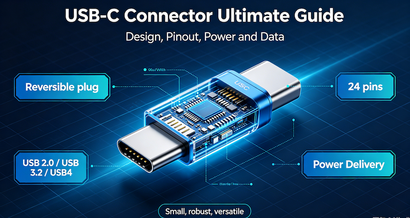
USB-C Connector Ultimate Guide
You are designing the next generation of a portable medical device. The product requires high-speed data transfer, 100W power delivery for fast...