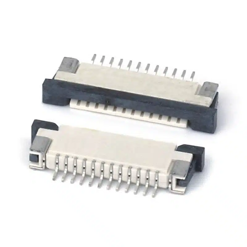
From 0.3mm ultra‑fine pitch to robust 1.0mm ZIF connectors — browse 500+ FPC connector models with instant 2D/3D downloads, free samples, and 3‑day delivery. Supported by real installation videos and live engineering assistance.
| Pitch | Lock Type | Contact Position | Mounting | Pin Range | Voltage/Current | Operating Temp. |
|---|---|---|---|---|---|---|
| 0.3 mm | Back Flip / Front Flip | Bottom / Top | SMT Horizontal | 9 – 61 | 30V / 0.2A | -40°C to +85°C |
| 0.5 mm | Flip Lock / Slide Lock | Top, Bottom, Dual | SMT, Vertical, Right‑Angle | 4 – 60 | 50V / 0.5A | -40°C to +105°C |
| 1.0 mm | Drawer Lock / Non‑ZIF | Top / Bottom | SMT, DIP, Vertical | 2 – 30 | 100V / 1.0A | -40°C to +105°C |


Enables compact PCB layouts in wearables, camera modules, and drones. Gold‑plated contacts guarantee low contact resistance <30 mΩ.
Choose from Front Flip, Back Flip, Slide Lock, Drawer Lock, and Non‑ZIF. Actuator designs withstand repeated mating without cracking.
Single connector accommodates both straight and reversed FPC cable insertion, reducing inventory and simplifying assembly.
Housings molded from Liquid Crystal Polymer (UL 94V‑0) survive lead‑free reflow up to 260°C. Ideal for automotive and industrial.
All SMT connectors supplied on standard 24mm/32mm reels for seamless pick‑and‑place assembly. Moisture‑sensitive level (MSL) 1.
Fully compliant with RoHS 3, REACH SVHC, and IPC‑620 soldering standards. Full material declaration available on request.
Over 12 million FPC connectors shipped annually from our ISO 9001 factory. We supply tier‑1 automotive, medical, and consumer brands.
Instant download of 2D drawings, 3D STEP files, and PCB footprints. Request a free sample to test fit and contact retention before committing.
Standard connectors ready to ship. Custom pin counts and OEM/ODM variations prototyped in just 5 days.
Watch step‑by‑step FPC connector installation videos filmed in our lab — and book a video call with an engineer when you get stuck.
Smartphones, tablets, laptops — low‑profile 0.5mm FPC connectors for LCD, camera, and battery interconnects.
Infotainment, ADAS cameras, LED lighting — 1.0mm pitch connectors with high vibration resistance and wide temp range.
Patient monitors, portable ultrasound, insulin pumps — ultra‑reliable ZIF contacts with zero insertion force.
HMI displays, servo drives, PLC modules — rugged right‑angle and vertical FPC connectors for harsh environments.
LED walls, digital signage, thin‑film transistors — 0.5mm/1.0mm top‑contact connectors for easy panel assembly.
Smartwatches, fitness bands, AR glasses — 0.3mm ultra‑fine pitch connectors saving board space in miniature designs.
An FPC connector (Flexible Printed Circuit connector) is a compact electromechanical component designed to link flexible flat cables or flexible printed circuits to a rigid PCB. Originally developed for miniaturised consumer electronics, the FPC connector has become a cornerstone of modern interconnect design, enabling high‑density, lightweight, and dynamic connections that rigid pin headers cannot achieve. Today, you will find FPC connector solutions in virtually every smartphone, laptop, automotive camera module, and wearable device.
Unlike traditional wire‑to‑board systems, an FPC connector uses a series of closely spaced contacts (typically gold‑plated copper alloy) that mate with exposed traces on the flexible circuit. The most common variants are ZIF (Zero Insertion Force) connectors, which employ a flip‑lock or slide‑lock actuator to clamp the cable without damaging the delicate conductors. According to Wikipedia’s flexible electronics entry, the technology behind flexible circuit interconnects has been refined over decades, enabling consumer devices to become thinner and more reliable.
A correctly selected FPC connector not only guarantees stable electrical performance but also simplifies assembly and reduces field returns. Whether you are designing a low‑cost consumer gadget or a safety‑critical automotive control unit, understanding the fundamentals of an FPC connector is the first step toward a successful product.
The term FPC connector covers a wide range of internal architectures, and choosing the wrong type is one of the most frequent design mistakes. The four main classification dimensions are locking mechanism, contact pitch, contact position, and mounting orientation.
A ZIF FPC connector allows the flexible cable to be inserted with practically zero force. After insertion, a rotating or sliding actuator locks the cable in place. This design protects the delicate traces during repeated mating cycles and is the preferred choice for display, touchscreen, and camera applications. In contrast, a Non‑ZIF FPC connector relies on a simple friction fit, which reduces component cost but requires more careful handling. Non‑ZIF styles are still common in low‑cycle applications such as battery interconnects inside sealed enclosures.
FPC connector pitch — the distance between adjacent contact centres — defines the overall connector width and required PCB routing density. The industry’s most popular pitches are:
When selecting pitch, always consider the FPC connector mating height and the overall stack‑up tolerances of your enclosure.
A top contact FPC connector makes electrical contact on the side of the cable facing away from the PCB; a bottom contact version mates on the cable side facing the board. Dual contact FPC connectors feature spring contacts on both sides, allowing the same connector to accept cables inserted in either orientation — an invaluable feature when managing multiple cable routing directions.
Engineers often use the terms FPC connector and FFC connector interchangeably, but the cables themselves differ. FPC (Flexible Printed Circuit) is a custom‑designed flex circuit with etched copper traces, often with a polyimide stiffener and specific fold lines. FFC (Flexible Flat Cable) is a mass‑produced, pre‑terminated flat cable with straight conductors laminated in polyester. While both can be mated with the same FPC connector, the cable thickness and stiffener design must be compatible with the connector’s actuator range. Molex’s FFC/FPC connector guide provides additional details on cable compatibility. Generally, an FPC connector specified for a 0.3mm thick cable will accept a standard FFC, but always verify the actuator’s clamping range to prevent intermittent connections.
Selecting the optimal FPC connector can be reduced to six engineering decisions. Follow this sequence to avoid costly redesigns.
Step 1 – Determine the Required Pitch. Start with the available board real estate and the number of signals. High‑density designs with more than 30 positions may benefit from a 0.3mm FPC connector, while low‑cost designs often prefer 0.5mm or 1.0mm.
Step 2 – Define Pin Count. FPC connector pin counts range from 2 to over 80 positions. Always specify a few spare pins for future firmware upgrades or test points.
Step 3 – Choose Contact Position. Match the contact orientation to the cable entry direction. If the cable approaches horizontally from the top, a top‑contact FPC connector keeps the cable flat. If the cable rises from the board surface, a vertical mount connector might be more ergonomic.
Step 4 – Select Lock Type. Evaluate the number of mating cycles and the operator’s skill level. For field‑replaceable modules, a robust flip‑lock FPC connector with an audible click is recommended. For factory‑only assembly, a cost‑effective slide‑lock may suffice.
Step 5 – Choose Mounting Style. Surface‑mount (SMT) is the default for automated assembly. Through‑hole (DIP) FPC connector variants offer superior mechanical retention but consume more board area. Right‑angle and vertical orientations depend on the cable routing plane.
Step 6 – Download the 3D Model. Before finalising the BOM, import the FPC connector STEP file into your CAD environment and check for interference with adjacent components, shields, and enclosure walls. Our FPC connector product pages provide immediate downloads in multiple formats.
Even the highest‑quality FPC connector will fail if installed incorrectly. Below are field‑proven guidelines.
1. Actuator Opening: Always release the lock with a dedicated plastic tool or a clean fingertip. Metal tweezers can scratch the actuator and compromise retention. If you are new to the process, watch our FPC Connector Installation Video embedded above on this page for a slow‑motion demonstration.
2. Cable Insertion Depth: The FPC must bottom out evenly against the connector’s rear wall. An improperly seated cable can cause intermittent contact and slow oxide build‑up. Some FPC connector models include visual alignment marks on the actuator.
3. Actuator Closing Force: Apply uniform pressure near the centre of the actuator until it latches. Avoid pressing on one corner, which can crack the housing. If the FPC connector actuator does not close smoothly, remove the cable and check for debris or bent contacts.
4. Soldering Profile: Follow JEDEC J‑STD‑020 reflow profiles. Our LCP‑bodied FPC connector parts withstand peak temperatures up to 260°C. Hand‑soldering is possible for DIP variants, but SMT parts must be reflowed.
The automotive environment subjects FPC connector components to extreme temperature cycling, vibration, and humidity. When choosing a FPC connector for advanced driver‑assistance systems (ADAS) or infotainment, look for high‑temperature LCP housings rated for -40°C to +125°C, selective gold plating of at least 0.2µm, and validated locking mechanisms that survive 30g mechanical shock. Several global connector standards, such as USCAR‑2, can serve as a benchmark. Our automotive‑grade FPC connector range has been qualified by leading tier‑1 suppliers and includes dual‑contact redundancy for safety‑critical signals.
Medical electronics demand FPC connector reliability above all else. Pacemakers, hearing aids, and portable diagnostic equipment use ultra‑fine pitch FPC connector parts to interconnect flex circuits with rigid sensor boards. Key characteristics include high mating‑cycle durability (10,000+ cycles), corrosion‑resistant contact alloys, and bio‑compatible housing materials. All medical FPC connector products we ship include full lot traceability and ISO 13485‑compliant documentation on request.
The global FPC connector market continues to be driven by demand for thinner, more reliable connections in 5G smartphones, foldable displays, and AR/VR headsets. Research by Bishop & Associates highlights a compound annual growth rate of over 6% for fine‑pitch interconnects through 2028. The shift from 0.5mm to 0.3mm FPC connector footprints is accelerating, pushing PCB fabricators to adopt laser‑drilled microvias and embedded trace technologies. At the same time, signal integrity concerns are becoming relevant even for traditional FPC connector designs, with differential pairs requiring controlled impedance routing through the connector interface.
With 17 years focused on FPC connector manufacturing, Vista Electronics has become a trusted partner for OEMs across 40 countries. Our in‑house moulding, stamping, and automated assembly lines ensure consistent quality, while our application engineers help you select the right FPC connector within hours — not days. We offer free 2D/3D drawings, free samples, and a 3‑day lead time on standard FPC connector models. Whether you need a single prototype or a container of high‑volume production, we deliver the same FPC connector excellence that top brands rely on.

A design team once spent three weeks debugging an intermittent display flicker on a new portable medical device. The root cause wasn’t...
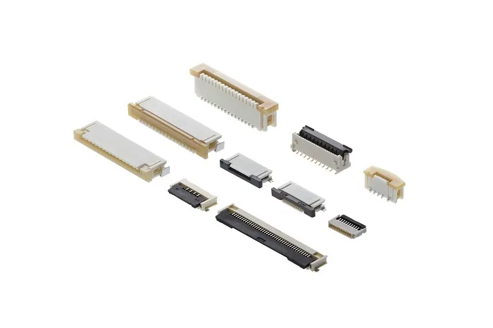
Learn how to select the right FPC connector pitch—0.3mm, 0.5mm, or 1.0mm. Compare density, mechanical strength, applications, and key selection factors for...

Complete guide to FPC connector types—pitch options, top vs bottom contact, ZIF vs non-ZIF, mounting styles, and locking mechanisms. Learn how to...