
Complete guide to FPC connector types—pitch options, top vs bottom contact, ZIF vs non-ZIF, mounting styles, and locking mechanisms. Learn how to choose the right FPC connector for your design.
You are laying out a new smartphone display module. The PCB is densely packed, the display driver needs to connect to the main board through a flexible circuit, and the available height above the board is less than 2mm. The engineering team is debating: 0.3mm or 0.5mm pitch? Top contact or bottom contact? ZIF or non-ZIF? The wrong choice means a respin, a delayed product launch, or a field failure.
This is the reality of modern electronics design. FPC connectors are everywhere—smartphones, tablets, laptops, automotive displays, medical devices, and industrial control panels. They are the critical interface between rigid PCBs and flexible circuits, enabling the compact, high-density interconnections that modern devices demand.
But with that capability comes complexity. FPC connectors are classified by pitch, contact position, mounting style, locking mechanism, and actuator type. Each combination serves a different application, and specifying the wrong one can derail a design.
This guide covers everything you need to know about FPC connector types: pitch options, contact configurations, mounting styles, locking mechanisms, and how to choose the right connector for your application.
Internal link: For a complete overview of FPC connectors, see our FPC Connector Category .
What Is an FPC Connector?
An FPC (Flexible Printed Circuit) connector is an electrical connector designed to connect a flexible printed circuit to a printed circuit board (PCB) or another electronic component. FPC connectors are high-density, lightweight, and compact, with pin counts ranging from as few as 4 to over 100 positions.
FPC connectors are often grouped with FFC (Flexible Flat Cable) connectors because they serve similar functions and use the same physical interfaces. However, there is a distinction: FPC connectors are designed specifically to interface with flexible printed circuit boards—circuits etched on flexible substrates like polyimide—while FFC connectors terminate flat ribbon cables.
Key characteristics of FPC connectors:
- Compact footprint: Ideal for space-constrained PCB designs
- High density: Fine pitches from 0.3mm to 1.25mm
- ZIF (Zero Insertion Force) options: Reduce assembly damage and enable repeated mating
- Multiple mounting styles: Right-angle, vertical, and surface mount
- Multiple contact positions: Top, bottom, or dual contact
FPC connectors are widely used in smartphones, tablets, LCD displays, automotive electronics, medical devices, and industrial control systems.
Internal link: Explore our full range of FPC Connectors —available in 0.3mm, 0.5mm, and 1.0mm pitches with multiple contact and locking options.
FPC Connector Types by Pitch
Pitch is the center-to-center distance between adjacent contacts. It is the most fundamental specification when selecting an FPC connector because it determines the connector’s density and the minimum spacing requirements for your PCB layout.
The most common pitches for FPC connectors are 0.3mm, 0.5mm, and 1.0mm. Each serves a different application space.
0.3mm Pitch FPC Connectors
0.3mm pitch is the finest pitch commonly available in production FPC connectors. These connectors are used in the most space-constrained applications where every millimeter of board space counts.
Key characteristics:
- Ultra-compact: The smallest footprint among common FPC connectors
- Staggered pin design: 0.3mm pitch connectors often use a staggered pin arrangement with a 0.6mm mounting pitch to reduce the mounting area
- Low profile: Ideal for ultra-thin devices
Typical applications:
- Smartphones and tablets
- Wearable devices
- Ultra-compact display modules
- Camera modules
0.5mm Pitch FPC Connectors
0.5mm pitch is the industry standard for FPC connectors. It offers the best balance of density, manufacturability, and reliability.
Key characteristics:
- Industry standard: The most widely used pitch
- Wide availability: Available from multiple manufacturers in numerous configurations
- Pin counts: Typically 6 to 80 conductors
Typical applications:
- LCD and OLED display connections
- Touch panel interfaces
- Main board to daughter board connections
- Consumer electronics
Internal link: Browse our 0.5mm Pitch FPC Connectors —available in top contact, bottom contact, and ZIF configurations.
1.0mm Pitch FPC Connectors
1.0mm pitch connectors are used in applications where board space is less constrained but mechanical robustness is more important.
Key characteristics:
- Larger footprint: More PCB space required
- Higher mechanical strength: More robust contacts and housing
- Pin counts: Typically 4 to 50 conductors
Typical applications:
- Industrial control panels
- Automotive electronics
- Power supply connections
- Applications requiring higher current capacity
Other Pitches
Less common pitches include 0.4mm, 0.6mm, 0.8mm, and 1.25mm. These are used in specialized applications where standard pitches do not fit the design requirements.
| Pitch | Density | Typical Applications |
|---|---|---|
| 0.3mm | Ultra-high | Smartphones, wearables, camera modules |
| 0.5mm | High (standard) | Displays, touch panels, consumer electronics |
| 1.0mm | Moderate | Industrial, automotive, power connections |
Internal link: For a deeper comparison of pitch options, see our FPC Connector Pitch Guide .
FPC Connector Types by Contact Position
The contact position determines which side of the FPC makes electrical contact with the connector terminals. This is a critical specification because it affects cable routing, board layout, and assembly.
Top Contact FPC Connectors
In a top contact connector, the electrical contacts are exposed on the top side of the connector. The FPC must be inserted with its contact pads facing upward.
When to use: If the FPC contact pads face upward (away from the PCB), use a top contact version.
Applications:
- Designs where the FPC routes over the top of the connector
- Stacked board configurations
Bottom Contact FPC Connectors
In a bottom contact connector, the electrical contacts are exposed on the bottom side of the connector. The FPC must be inserted with its contact pads facing downward.
When to use: If the FPC contact pads face downward (toward the PCB), use a bottom contact version.
Applications:
- Designs where the FPC routes under the connector
- Space-constrained layouts
Dual Contact FPC Connectors
Dual contact connectors have contacts on both the top and bottom sides of the connector. They can accommodate an FPC in either orientation.
Advantages:
- Flexibility: The FPC can be inserted in either orientation
- Simplified assembly: No need to verify cable orientation
Trade-offs:
- Slightly higher cost
- May have different retention force specifications for top and bottom contacts
FPC Connector Types by Mounting Style
FPC connectors are available in several PCB mounting configurations. The choice affects mechanical strength, assembly process, and PCB footprint.
Right-Angle (Horizontal) FPC Connectors
Right-angle connectors are mounted with the insertion axis parallel to the PCB. The FPC is inserted horizontally, parallel to the board surface.
Advantages:
- Low profile: Minimal height above the PCB
- Edge-mount compatible: Ideal for board-edge connections
- Most common orientation: Widely available in all pitch and contact configurations
Trade-offs:
- Requires PCB edge clearance for cable routing
- May require more board area in the X-Y plane
Best for: Edge-mounted designs, display connections, and any application where height is the primary constraint.
Vertical FPC Connectors
Vertical connectors are mounted with the insertion axis perpendicular to the PCB. The FPC is inserted vertically, standing up from the board surface.
Advantages:
- Minimal PCB footprint: Takes up less board area than right-angle connectors
- Top-entry design: Cable enters from above the board
Trade-offs:
- Higher profile: Requires more clearance above the PCB
- Less common: Fewer options available than right-angle
Best for: Designs where board area is the primary constraint and height is available.
Right-Angle with Top or Bottom Contact
Right-angle connectors can be combined with top or bottom contact configurations. This allows designers to optimize both the mounting orientation and the cable routing direction.
Internal link: Explore our FPC Connector Mounting Options —available in right-angle and vertical orientations with top, bottom, and dual contact options.
FPC Connector Types by Locking Mechanism
The locking mechanism determines how the FPC is secured in the connector. This is one of the most important selection criteria for engineers because it affects assembly ease, retention force, and mating cycle life.
ZIF (Zero Insertion Force) FPC Connectors
ZIF connectors use an actuator (flip-lock, slide-lock, or back-flip) to secure the FPC after insertion. The actuator is opened, the FPC is inserted with minimal force, and the actuator is closed to clamp the FPC in place.
Key characteristics:
- Zero insertion force: The FPC is inserted with no resistance
- Actuator mechanism: Flip-lock, slide-lock, or back-flip
- High retention force: The actuator provides strong mechanical clamping
- Increased mating cycles: Less wear on contacts allows for more insertions
- Better for high vibration: Superior retention in automotive and industrial applications
Advantages:
- Reduced assembly damage: No force is applied during insertion
- Higher mating cycle life: Can exceed 100,000 cycles
- Superior retention: Ideal for high-vibration environments
Trade-offs:
- More expensive: Additional actuator mechanism adds cost
- More complex assembly: Requires opening and closing the actuator
- Larger footprint: The actuator adds height and width
Applications:
- Smartphone display connections
- Automotive electronics
- High-reliability applications
- Applications requiring frequent mating/unmating
Types of ZIF actuators:
- Flip-lock (Front Flip): The actuator flips forward to lock the cable
- Back-flip: The actuator flips backward
- Slide-lock: The actuator slides horizontally to lock
- Lifting cover: The cover lifts to allow insertion
Internal link: Browse our ZIF FPC Connectors —available in 0.3mm, 0.5mm, and 1.0mm pitches with flip-lock and slide-lock actuators.
Non-ZIF FPC Connectors
Non-ZIF connectors rely on friction to secure the FPC. The FPC is inserted directly into the connector, and the friction between the contacts and the FPC provides the retention force.
Key characteristics:
- Direct insertion: The FPC is pushed directly into the connector
- Friction retention: No actuator mechanism
- Simpler design: Fewer moving parts
- Smaller footprint: No actuator adds height or width
Advantages:
- Lower cost: No actuator mechanism
- Smaller footprint: Ideal for space-constrained designs
- Simpler assembly: Insert and done—no actuator to open and close
- Lower profile: No actuator adds height
Trade-offs:
- Insertion force: The FPC must be pushed in with some force
- Lower mating cycle life: Contact wear from friction during insertion
- Lower retention force: Less secure in high-vibration environments
- More prone to damage: Improper insertion can damage contacts
Applications:
- Permanent or semi-permanent assemblies
- Applications where connections are not frequently changed
- Cost-sensitive designs
- Space-constrained designs
LIF (Low Insertion Force) FPC Connectors
LIF connectors are an intermediate option between ZIF and non-ZIF. They require some insertion force but less than traditional non-ZIF connectors.
Key characteristics:
- Low insertion force: Less than non-ZIF but more than ZIF
- No actuator: Similar to non-ZIF in design
- Better than non-ZIF: Reduced insertion force minimizes contact damage
ZIF vs Non-ZIF FPC Connector: Comparison
| Feature | ZIF | Non-ZIF |
|---|---|---|
| Actuator | Yes (flip, slide, or back-flip) | No |
| Insertion Force | Zero | Required |
| Mating Cycles | Higher (up to 100,000+) | Lower |
| Retention Force | Higher | Lower |
| Vibration Resistance | Excellent | Moderate |
| Footprint | Larger | Smaller |
| Cost | Higher | Lower |
| Assembly | Two steps (insert + close) | One step (insert) |
| Best For | High-reliability, frequent mating | Cost-sensitive, space-constrained |
How to Choose the Right FPC Connector
Selecting the right FPC connector requires balancing multiple factors: pitch, contact position, mounting style, locking mechanism, and application requirements.
Step 1: Determine the Required Pitch
- Ultra-compact device (smartphone, wearable)? → 0.3mm
- Standard consumer electronics (display, touch panel)? → 0.5mm
- Industrial or automotive (high reliability)? → 1.0mm
Step 2: Select the Contact Position
- FPC pads face up? → Top contact
- FPC pads face down? → Bottom contact
- Orientation unknown or variable? → Dual contact
Step 3: Choose the Mounting Style
- Height is the primary constraint? → Right-angle
- Board area is the primary constraint? → Vertical
- Edge-mounted design? → Right-angle
Step 4: Select the Locking Mechanism
- High vibration environment? → ZIF
- Frequent mating/unmating? → ZIF
- Cost-sensitive design? → Non-ZIF
- Space-constrained design? → Non-ZIF
Step 5: Verify Pin Count and Cable Thickness
- Pin count: Ensure the connector has enough positions for your signal count
- Cable thickness: Verify the connector is compatible with your FPC thickness (typically 0.12mm to 0.3mm)
Step 6: Consider Environmental Requirements
- Operating temperature: Standard (-25°C to +85°C) or extended
- Vibration: ZIF for high-vibration environments
- Moisture: Sealed options for harsh environments
Common Mistakes When Choosing FPC Connectors
Mistake 1: Confusing top contact and bottom contact
Top contact and bottom contact connectors require different FPC orientations. Using the wrong one means the FPC will not make electrical contact.
Solution: Verify the FPC pad orientation before selecting the connector.
Mistake 2: Choosing non-ZIF for high-vibration applications
Non-ZIF connectors rely on friction for retention—not sufficient for high-vibration environments like automotive or industrial applications.
Solution: Specify ZIF connectors for any application subject to vibration.
Mistake 3: Ignoring the actuator type
Different ZIF actuators (flip-lock, slide-lock, back-flip) have different assembly requirements and height profiles.
Solution: Verify the actuator type is compatible with your assembly process and enclosure.
Mistake 4: Overlooking cable thickness compatibility
FPC connectors are designed for specific cable thicknesses. Using the wrong thickness can result in poor contact or damaged connectors.
Solution: Check the connector datasheet for the compatible FPC thickness range.
Mistake 5: Forgetting about the number of pins
FPC connectors are available in specific pin counts. If your design requires a non-standard count, you may need a custom solution.
Solution: Design around standard pin counts (4, 6, 8, 10, 12, 14, 16, 19, 20, 24, 26, 28, 30, 32, 36, 40, 45, 50, 60, 65, 80, etc.).
Applications of FPC Connectors
FPC connectors are used across virtually every industry that requires compact, high-density interconnections.
Consumer Electronics:
- Smartphones and tablets
- Laptops and notebooks
- Wearable devices
- Digital cameras and camcorders
- Gaming consoles
Display and Touch:
- LCD and OLED display connections
- Touch panel interfaces
- E-paper displays
Automotive:
- Infotainment systems
- Dashboard displays
- Camera modules
- Interior lighting
Medical Devices:
- Patient monitors
- Diagnostic equipment
- Portable medical instruments
Industrial:
- Control panels and HMIs
- Industrial cameras
- Test and measurement equipment
Communication:
- Networking equipment
- Telecom infrastructure
Internal link: For FPC connector applications in specific industries, see our FPC Connector Category .
Frequently Asked Questions
What are the different types of FPC connectors?
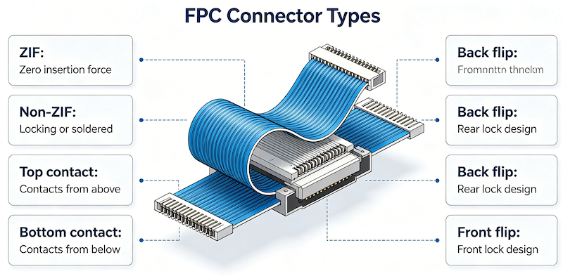
FPC connectors are classified by pitch (0.3mm, 0.5mm, 1.0mm), contact position (top, bottom, dual), mounting style (right-angle, vertical), locking mechanism (ZIF, non-ZIF, LIF), and actuator type (flip-lock, slide-lock, back-flip).
What is the difference between ZIF and non-ZIF FPC connectors?
ZIF (Zero Insertion Force) connectors use an actuator to secure the FPC after insertion. The FPC is inserted with no force, and the actuator is closed to clamp it in place. Non-ZIF connectors rely on friction between the contacts and the FPC for retention. ZIF offers higher retention and more mating cycles but costs more and takes up more space.
What is the difference between top contact and bottom contact?
Top contact connectors require the FPC to be inserted with its contact pads facing upward. Bottom contact connectors require the FPC to be inserted with its contact pads facing downward. Dual contact connectors accept either orientation.
How do I choose the correct FPC connector?
Start with pitch (0.3mm for ultra-compact, 0.5mm for standard, 1.0mm for industrial), then select contact position (top, bottom, or dual), mounting style (right-angle or vertical), and locking mechanism (ZIF or non-ZIF) based on your application requirements.
What pitch FPC connector should I use?
0.3mm for ultra-compact devices like smartphones and wearables. 0.5mm for standard consumer electronics like displays and touch panels. 1.0mm for industrial, automotive, and applications requiring higher mechanical robustness.
What is the typical pin count for FPC connectors?
FPC connectors are available in a wide range of pin counts, typically from 4 to 80 pins for 0.5mm pitch and 4 to 50 pins for 1.0mm pitch. Custom pin counts may be available.
What is the difference between FPC and FFC connectors?
FPC (Flexible Printed Circuit) connectors are designed to interface with flexible printed circuit boards—circuits etched on flexible substrates. FFC (Flexible Flat Cable) connectors are designed to terminate flat ribbon cables. Both use the same physical interfaces and are often grouped together.
Do you offer custom FPC connector solutions?
Yes. Vistar Electronics supports OEM and ODM customization for FPC connectors, including custom pin counts, contact plating, actuator type, and packaging. Contact our engineering team for specific requirements.
FPC Connectors from Vistar Electronics
At Vistar Electronics, we understand the nuances of FPC connector selection. Our FPC connector portfolio includes:
- Multiple pitches: 0.3mm, 0.5mm, and 1.0mm
- Multiple contact positions: Top contact, bottom contact, dual contact
- Multiple mounting styles: Right-angle and vertical
- Multiple locking mechanisms: ZIF (flip-lock, slide-lock, back-flip) and non-ZIF
- Pin counts: Customizable to your requirements
- Contact plating: Gold-plated for reliable signal integrity
- RoHS and REACH compliant
- OEM and ODM customization available
Whether you are designing a smartphone display module, an automotive infotainment system, or an industrial control panel, the right FPC connector starts with understanding the pitch, contact position, mounting style, and locking mechanism requirements. We can help you specify it, source it, and integrate it.
For technical specifications, samples, or application support, contact the Vistar Electronics engineering team.


