Learn how to select the right FPC connector pitch—0.3mm, 0.5mm, or 1.0mm. Compare density, mechanical strength, applications, and key selection factors for your PCB design.
You are laying out the display interface for a new smartphone. The PCB is densely packed with components, the available board width for the connector is less than 5mm, and the display FPC has 40 signal lines that must all connect to the main board. The engineering team is debating: 0.3mm or 0.5mm pitch? One engineer argues for the space savings of 0.3mm; another insists that 0.5mm is the safer, more manufacturable choice.
This is one of the most critical decisions in FPC connector selection—and one that has far-reaching implications for PCB space, assembly yield, mechanical reliability, and total cost of ownership. The pitch determines how many signals can fit in a given board width, how robust the connector will be, how easily it can be assembled, and whether the design can be manufactured at scale.
For PCB designers, mechanical engineers, and procurement professionals, understanding FPC connector pitch selection is essential for avoiding costly respins, field failures, and assembly bottlenecks.
This guide covers everything you need to know: what pitch is, why it matters, the most common pitch sizes, how they compare, and how to choose the right pitch for your application.
Internal link: For a complete overview of FPC connector types and specifications, see our FPC Connector Product Center .
What Is FPC Connector Pitch?
Pitch is the center-to-center distance between adjacent contacts on a connector. It is the most fundamental specification of an FPC connector—it determines the connector’s density, width, signal-carrying capacity, and mechanical robustness.
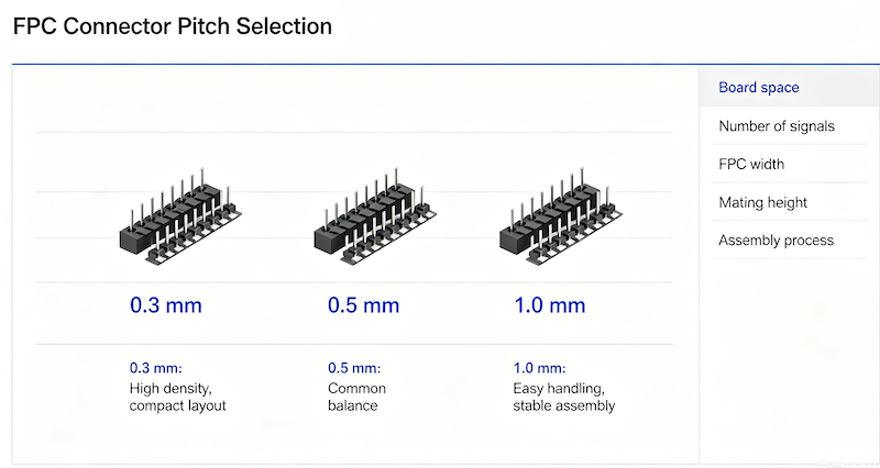
Pitch is typically measured in millimetres (mm). The most common pitches for FPC connectors are 0.3mm, 0.5mm, and 1.0mm. Other pitches, such as 0.4mm, 0.8mm, 1.25mm, and 2.54mm, are also available for specialized applications.
How pitch is measured: Pitch is measured from the center of one contact to the center of the adjacent contact. For example, in a 0.5mm pitch connector, the distance between the center of pin 1 and the center of pin 2 is exactly 0.5mm.
The pitch directly determines:
- Connector width: Finer pitch means narrower connectors
- PCB footprint: Finer pitch requires more precise PCB layout
- Number of pins: Finer pitch allows more signals in the same board space
- Manufacturing cost: Finer pitch generally increases cost
Internal link: For a step-by-step selection framework covering pitch, actuator type, and contact structure, see our guide How to Select the Right FPC/FFC Connector .
Why Pitch Selection Matters
Choosing the wrong pitch can have cascading consequences across the entire product lifecycle:
PCB Space: The pitch determines how many signals can fit in a given board width. A 0.3mm pitch connector with 40 pins is significantly narrower than a 0.5mm pitch connector with the same pin count. This can be the difference between fitting on the board and requiring a respin.
Mechanical Strength: Finer pitch connectors are inherently more delicate. The contacts are smaller, the housing is thinner, and the margins for manufacturing error are tighter. A 1.0mm pitch connector offers significantly higher mechanical robustness than a 0.3mm pitch connector.
Assembly Yield: Finer pitch connectors require more precise assembly. Pick-and-place machines must be calibrated more accurately, solder paste deposition must be more consistent, and inspection must be more thorough. This translates to higher assembly costs and lower first-pass yields.
Signal Integrity: Finer pitch connectors have smaller contact surfaces and tighter spacing between adjacent signals. This increases the risk of crosstalk, especially at higher frequencies. For high-speed signals, pitch selection must consider impedance control and signal isolation.
Total Cost: Finer pitch connectors are more expensive to manufacture, require more expensive PCBs (finer traces, tighter tolerances), and increase assembly costs. The total cost of ownership must consider not just the component price but also the PCB, assembly, and field reliability costs.
Common FPC Connector Pitch Sizes
0.3mm Pitch FPC Connectors
0.3mm pitch is the finest pitch commonly available in production FPC connectors. These connectors are used in the most space-constrained applications where every millimetre of board space counts.
Key characteristics:
- Ultra-compact: The smallest footprint among common FPC connectors
- High-density: Enables more signals in less board space
- Precision required: Demands high standards for manufacturing, PCB layout, and FPC cable quality
- ZIF design: Most 0.3mm pitch connectors use ZIF (Zero Insertion Force) mechanisms to protect delicate contacts
Typical applications:
- Smartphone mainboards and display modules
- Foldable phone hinges
- Ultra-narrow bezel displays in premium smartphones
- Camera modules in compact devices
- Minimally invasive medical devices
- Military-grade headsets
Trade-offs:
- High cost
- Stringent assembly requirements
- Lower mechanical strength
- More susceptible to damage during assembly and service
Internal link: Explore our 0.3mm ZIF FPC Connector —featuring front-flip actuator design for intuitive assembly and superior cable retention in vibration-prone environments.
0.5mm Pitch FPC Connectors
0.5mm pitch is the industry standard and the most widely used FPC connector pitch. It offers the best balance of density, reliability, and cost.
Key characteristics:
- Industry standard: The de facto standard for FPC connectors
- Balanced: Excellent trade-off between density and manufacturability
- Mature supply chain: Highly competitive pricing
- Wide availability: Available from multiple manufacturers in numerous configurations
Typical applications:
- Mobile phone displays
- Touch panel interfaces
- Board-to-board interconnects
- Camera modules
- Tablets and laptops
- Drones
- Most consumer and industrial electronics
Trade-offs:
- Requires reasonable assembly precision
- Not suitable for ultra-compact devices where 0.3mm is required
Internal link: Browse our 0.5mm Pitch ZIF FPC Connector Top Contact —designed with a precision flip-lock actuator for zero-force insertion and long-term reliability in high-density applications.
1.0mm Pitch FPC Connectors
1.0mm pitch is the oldest and most universal FPC connector specification. These connectors are used in applications where space constraints are less critical and mechanical robustness is more important.
Key characteristics:
- Universal: The earliest, most widely used pitch
- Robust: Connector body and contacts are relatively strong
- Lower precision required: More forgiving manufacturing tolerances
- Lower cost: Most cost-effective option
Typical applications:
- Home appliances
- Children’s toys
- Simple power or low-speed signal transmission
- Industrial control panels
- Applications where space constraints are not critical
- Cost-sensitive designs
Trade-offs:
- Largest volume
- Gradually being phased out in modern high-density designs
- Limited pin count in a given board width
Internal link: View our 1.0mm Pitch FPC Connector ZIF Top Contact —engineered for dependable interconnections with Zero Insertion Force design for simplified assembly and enhanced durability.
Pitch Comparison at a Glance
| Feature | 0.3mm Pitch | 0.5mm Pitch | 1.0mm Pitch |
|---|---|---|---|
| PCB Density | ★★★★★ (Ultra-high) | ★★★★ (High) | ★★ (Moderate) |
| Mechanical Strength | ★★ (Low) | ★★★★ (Good) | ★★★★★ (Excellent) |
| Assembly Precision Required | Very High | Moderate | Low |
| Component Cost | High | Moderate | Low |
| PCB Cost | High | Moderate | Low |
| Signal Density | Highest | High | Moderate |
| Consumer Electronics | Excellent | Excellent | Good |
| Industrial Applications | Limited | Good | Excellent |
| Typical Pin Count | Up to 80+ | Up to 80 | Up to 50 |
How to Choose the Right Pitch
Step 1: Determine the Required Signal Count
Start by counting the number of signals that must pass through the connector. This includes:
- Data lines
- Power lines
- Ground lines
- Control signals
Rule of thumb: The higher the signal count, the finer the pitch required to fit within the available board width.
Step 2: Measure Available PCB Space
Measure the available board width for the connector. Consider:
- PCB edge clearance
- Adjacent components
- Routing channels for traces
Calculation: Connector width ≈ (Number of pins × Pitch) + Housing width. A 40-pin 0.5mm connector is approximately 20mm wide, while a 40-pin 0.3mm connector is approximately 12mm wide.
Step 3: Consider Mechanical Requirements
- High vibration environment? Choose 0.5mm or 1.0mm—they offer better mechanical strength
- Frequent mating/unmating? Choose 0.5mm or 1.0mm—they are more durable
- Delicate FPC cable? Choose ZIF with finer pitch—ZIF reduces insertion force and protects the cable
Step 4: Evaluate Manufacturing Capability
- High-volume SMT assembly? 0.5mm is the most mature and reliable
- Prototype or low-volume? 0.5mm or 1.0mm are easier to assemble and rework
- Ultra-fine pitch (0.3mm)? Requires advanced assembly equipment and processes
Step 5: Assess Total Cost
Consider not just the component price but:
- PCB fabrication cost (finer pitch = tighter tolerances = higher cost)
- Assembly cost (finer pitch = more precise placement = higher cost)
- Inspection and test cost
- Field failure cost
Selection Decision Matrix
| Requirement | Recommended Pitch |
|---|---|
| Ultra-compact smartphone or wearable | 0.3mm |
| Standard consumer electronics (displays, touch panels) | 0.5mm |
| Industrial equipment, home appliances | 1.0mm |
| High signal count in limited board width | 0.3mm or 0.5mm |
| Maximum mechanical robustness | 1.0mm |
| Cost-sensitive design | 1.0mm or 0.5mm |
| High-volume automated assembly | 0.5mm |
| Prototype or low-volume production | 0.5mm or 1.0mm |
Common Mistakes in FPC Connector Pitch Selection
Mistake 1: Choosing 0.3mm for cost-sensitive consumer products
0.3mm connectors are significantly more expensive to manufacture and assemble. For standard consumer products where board space is not critically constrained, 0.5mm offers better value.
Solution: Only specify 0.3mm when board space is the absolute priority.
Mistake 2: Choosing 1.0mm for high-density designs
1.0mm pitch connectors cannot achieve the same pin density as 0.5mm or 0.3mm. For modern high-density designs, 1.0mm is often inadequate.
Solution: For designs with more than 30 signals, consider 0.5mm or finer pitches.
Mistake 3: Ignoring assembly capability
Specifying 0.3mm without verifying that your assembly partner can handle fine-pitch components leads to low yields and delays.
Solution: Check with your assembly partner before finalizing the pitch specification.
Mistake 4: Overlooking cable thickness compatibility
Finer pitch connectors are designed for specific FPC cable thicknesses. Using the wrong thickness can result in poor contact or damaged connectors.
Solution: Verify the connector’s compatible FPC thickness range before specifying.
Mistake 5: Forgetting about ZIF vs non-ZIF
Finer pitch connectors almost always use ZIF mechanisms to protect delicate contacts. Non-ZIF connectors at 0.5mm and 1.0mm are more common.
Solution: Consider the locking mechanism alongside pitch selection.
Typical Applications by Pitch
0.3mm Pitch Applications
- Smartphone display modules
- Foldable phone hinges
- Premium smartphone ultra-narrow bezel displays
- Camera modules
- Minimally invasive medical devices
- Military-grade headsets
0.5mm Pitch Applications
- Mobile phone displays
- Touch panel interfaces
- Board-to-board interconnects
- Camera modules
- Tablets and laptops
- Drones
- Consumer and industrial electronics
1.0mm Pitch Applications
- Home appliances
- Industrial control panels
- Power supply connections
- Simple low-speed signal transmission
Internal link: For a complete selection guide covering contact position, locking style, and mounting direction, see our FPC Connector Product Center .
Frequently Asked Questions
What is FPC connector pitch?
Pitch is the center-to-center distance between adjacent contacts on an FPC connector. It is measured in millimetres and determines the connector’s density, width, and mechanical robustness.
How do I measure FPC connector pitch?
Measure the distance from the center of one contact to the center of the adjacent contact. For a 0.5mm pitch connector, this distance is exactly 0.5mm.
Which pitch is best for smartphones?
0.3mm pitch is commonly used in premium smartphones for ultra-compact designs, while 0.5mm pitch is the industry standard for most smartphone display modules.
Is 0.3mm better than 0.5mm?
Neither is universally better. 0.3mm offers higher density and smaller footprint but comes with higher cost, lower mechanical strength, and more stringent assembly requirements. 0.5mm offers the best balance of density, reliability, and cost.
Can different pitch connectors be interchangeable?
No. Different pitch connectors have different footprints, PCB layouts, and cable requirements. They are not interchangeable without a PCB redesign.
How do I choose the correct FPC connector?
Start with signal count and available board space to determine the required pitch. Then consider mechanical requirements (vibration, mating cycles), manufacturing capability, and total cost. Finally, select contact position, locking style, and mounting direction.
What is the difference between 0.3mm, 0.5mm, and 1.0mm?
0.3mm is the finest pitch for ultra-compact, high-density applications. 0.5mm is the industry standard offering the best balance of density and reliability. 1.0mm is the most robust and cost-effective option for applications where space is not critical.
Do you offer custom pitch FPC connectors?
Yes. Vistar Electronics supports OEM and ODM customization for FPC connectors, including custom pin counts, contact plating, and mechanical modifications. Contact our engineering team for specific requirements.
FPC Connectors from Vistar Electronics
At Vistar Electronics, we understand the nuances of FPC connector pitch selection. Our FPC connector portfolio includes:
- Multiple pitches: 0.3mm, 0.5mm, 0.8mm, 1.0mm, 1.25mm, 2.0mm, and 2.54mm
- ZIF and non-ZIF locking mechanisms
- Top contact and bottom contact configurations
- Multiple mounting styles: SMT, right-angle, and vertical
- Gold-plated contacts for reliable signal integrity
- High-temperature-resistant materials
- RoHS 3 and REACH compliant
- OEM and ODM customization available
Whether you are designing a smartphone display module, an automotive infotainment system, or an industrial control panel, the right FPC connector starts with understanding the pitch, contact position, and locking mechanism requirements. We can help you specify it, source it, and integrate it.
Internal link: Browse our full range of FPC Connectors .
For technical specifications, samples, or application support, contact the Vistar Electronics engineering team.