

Through-Hole 1.0mm Pitch FFC/FPC Female Connector for PCB, Ribbon Cable & Industrial Control
The FPC-1025DL-nP is a 1.0mm FFC/FPC connector drawing type — a through‑hole 1.0mm pitch female FFC/FPC connector featuring a drawing (slide‑lock) mechanism, available in 4 to 20 positions (n = number of pins). Rated 0.5A, 50V, 20 mating cycles. Accepts standard 1.0mm pitch flexible flat cable (FFC) or flexible printed circuit (FPC). RoHS & REACH compliant. Tray/Tube packaging. MOQ 1,000 pcs. Free sample for qualified projects.
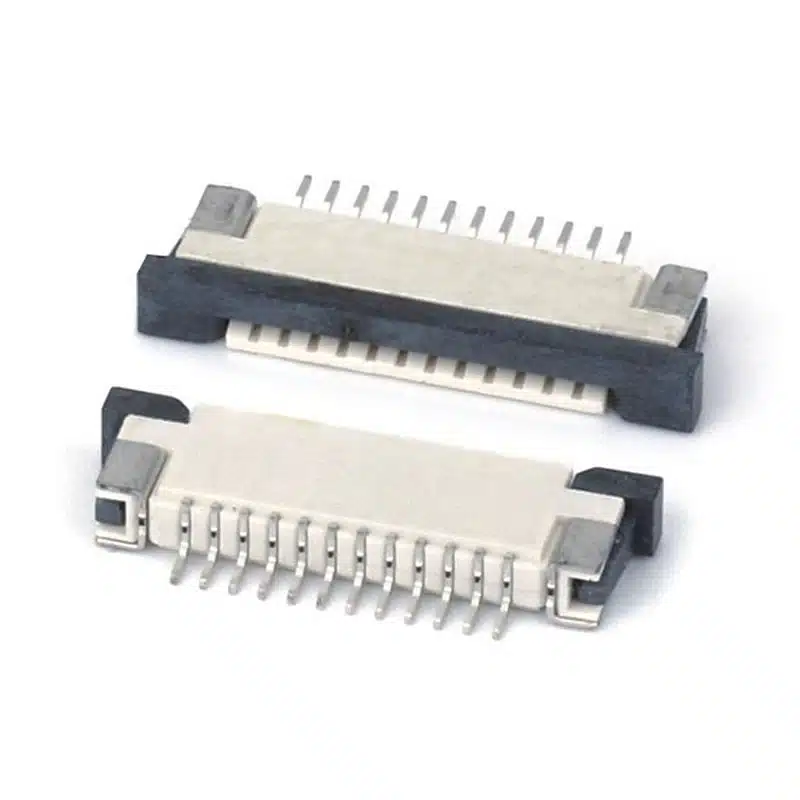
FPC-1025DL-nP Drawing Type Connector — 1.0mm FFC/FPC Through-Hole Connector Product Overview
The FPC-1025DL-nP drawing type connector is a reliable through‑hole FFC/FPC connector series designed for applications where a simple, mechanically robust cable‑to‑board connection is required. Unlike ZIF (zero insertion force) connectors that use a flip‑lock actuator, this 1.0mm FFC/FPC connector drawing type uses a slide‑locking mechanism that grips the inserted flexible cable securely, providing excellent vibration resistance and consistent contact force even after multiple insertions. The “n” in the part number denotes the number of positions (pins), ranging from 4 to 20, making the series highly versatile for everything from low‑pin‑count sensor connections to multi‑channel data buses.
With a standard 1.0mm contact pitch and a compact profile, the FPC-1025DL‑nP series integrates seamlessly into dense PCB layouts. The through‑hole mounting ensures strong mechanical anchoring, preventing pad lift during cable insertion and extraction. Gold‑plated phosphor bronze contacts deliver stable, low‑resistance connections, while the high‑temperature LCP housing withstands wave‑solder processes up to 260°C. Whether you are designing an industrial control panel, a medical device interface, or a consumer appliance, this drawing‑type connector provides a cost‑effective, durable alternative to more complex latching systems.
1.0mm FFC/FPC Drawing Type Connector nP — FPC-1025DL-nP Series Full Technical Specifications
| Parameter | Value | Notes |
|---|---|---|
| Part Number | FPC-1025DL-nP | n = 4, 6, 8, 10, 12, 14, 16, 18, 20 (specify when ordering) |
| Connector Type | FFC/FPC Female Connector | Accepts 1.0mm pitch FFC/FPC cable, 0.3mm thick |
| Actuation Type | Drawing (Slide‑lock) | No actuator; cable slides into contacts |
| Pitch | 1.0mm | Industry standard |
| Positions | 4–20 | Configurable by “n” |
| Mounting Style | Through‑Hole DIP (vertical) | Wave or hand soldering |
| Current Rating | 0.5A per contact | At 50V DC resistive load |
| Voltage Rating | 50V DC | — |
| Mating Cycles | 20 cycles | Drawing‑type durability; cable insertion/extraction |
| Contact Resistance | ≤20 mΩ (initial) | Gold over nickel |
| Insulation Resistance | ≥500 MΩ @ 250V DC | Between adjacent contacts |
| Dielectric Strength | 500V AC (1 minute) | No breakdown |
| Contact Material | Phosphor Bronze, Gold Plated | 0.76µm Au over Ni |
| Terminal Material | Brass, Gold over Nickel | Through‑hole solderable |
| Housing Material | LCP (UL94 V‑0), high‑temp | Wave‑solder compatible |
| Operating Temperature | −25°C to +85°C | Commercial & light‑industrial |
| Storage Temperature | −30°C to +85°C | — |
| Soldering Temperature | 260°C, 5s max (wave) | Per IEC 60068‑2‑20 |
| Packaging | Tray / Tube | Depending on pin count |
Why Engineers Choose the Through-Hole FFC/FPC Drawing Type Connector 1.0mm — Key Advantages
Simple & Robust Slide‑Lock Mechanism
No fragile actuator to break. The cable slides directly into the contact fingers and is held by friction and a physical stop, making this through-hole FFC/FPC drawing type connector 1.0mm ideal for applications subject to vibration or where the connector is rarely mated/unmated.
Configurable from 4 to 20 Positions
The FPC-1025DL‑nP series covers a wide range of I/O requirements with a single connector family. Specify n = 4, 6, 8, 10, 12, 14, 16, 18, or 20 pins to match your FFC/FPC cable exactly.
Through‑Hole DIP — Maximum Mechanical Anchoring
Pins pass through the PCB and are soldered on both sides, resisting pull‑out forces when the cable is removed. This is critical for connectors that may experience lateral stress during assembly or service.
RoHS & REACH Compliant, Wave‑Solder Ready
Fully compliant with RoHS 3 (2015/863) and REACH SVHC. The LCP housing withstands wave‑solder temperatures up to 260°C for 5 seconds. For further regulatory information, see the ECHA REACH regulation.
Where to Use the FFC FPC Connector Drawing Type 1.0mm PCB — Applications for Industrial, Medical & Consumer Electronics
PCB Layout & Wave Soldering Guidelines for the FPC-1025DL-nP Series
Recommended Footprint
The footprint varies with pin count. All positions use 1.0mm pitch, 2.54mm row spacing (if dual‑row; verify with datasheet). Pad hole diameter: 1.0mm for each terminal. Keep at least 3mm clearance behind the connector for cable insertion. The connector body should sit flush against the PCB before soldering.
Wave Soldering Profile
Pre‑heat PCB to 100–120°C for 60 seconds. Solder pot temperature 250–260°C, contact time 3–5 seconds. Ensure the connector is not submerged beyond its terminals. Allow gradual cooling at 4–6°C per second. The LCP housing is rated for these temperatures.
Manual Soldering
Use a 350°C iron with a 1.2mm chisel tip. Solder each terminal for ≤3 seconds. Work from the center pins outward to minimize thermal stress. After soldering, inspect for solder bridges between adjacent pads, especially at 1.0mm pitch.
Cable Insertion & Removal
Insert the FFC/FPC cable straight into the slot until it stops. Pull gently to confirm retention. To remove, pull the cable straight out; do not twist. The 20‑cycle rating is based on straight insertion/extraction with minimal side loading.
Drawing Type vs ZIF FFC/FPC Connectors: When Simplicity Wins
The 1.0mm FFC/FPC connector drawing type occupies a specific niche between low‑cost zero‑insertion‑force (ZIF) connectors and permanent solder joints. A ZIF connector requires a movable actuator (flip‑lock or slider) that can break if mishandled, and it adds to the component height. A drawing‑type connector eliminates the actuator entirely: the cable simply slides into the housing and is retained by spring‑loaded contacts and a physical end stop. This design reduces part count, eliminates a potential failure point, and often results in a lower profile — advantages that matter in space‑constrained or vibration‑prone environments. While the mating cycle count is lower (20 vs. 50–100 for ZIF), the drawing‑type connector excels in applications where the cable is connected once during assembly and rarely removed, such as internal sensor harnesses, fixed display connections, or industrial junction boxes. For these use cases, the drawing‑type connector offers a simpler, more robust, and cost‑effective solution.
Mechanical & Environmental Reliability Testing for the FPC-1025DL-nP Series
The FPC-1025DL‑nP series has passed qualification tests to ensure consistent performance across its 20‑cycle lifetime. Key test results include:
- Mating durability: 20 insertion/extraction cycles with a standard 1.0mm FFC cable. Contact resistance remained below 40 mΩ, and retention force stayed above 5 N.
- Vibration test: 10–500 Hz, 1.5mm amplitude, 2 hours per axis per IEC 60068‑2‑6. No momentary contact opening exceeding 1 µs.
- Thermal shock: 50 cycles between −30°C and +85°C per IEC 60068‑2‑14. No housing deformation or contact relaxation.
- Humidity aging: 96 hours at 40°C, 90–95% RH. Insulation resistance maintained above 100 MΩ, and no visible corrosion on gold‑plated contacts.
For full test reports, contact engineering@vistarelectronics.com.
Packaging, Compliance & Ordering Information
All FPC-1025DL-nP 1.0mm FFC/FPC connector units are shipped in antistatic trays or tubes depending on pin count. The connectors are fully lead‑free and compatible with SAC305 solder. To order, specify the complete part number, e.g., FPC-1025DL‑10P for a 10‑position version. Standard MOQ is 1,000 pieces. For a free sample or volume pricing, email sales@vistarelectronics.com with your company details, required pin count, and project application.
1.0mm FFC/FPC Connector Drawing Type — Frequently Asked Questions
What does the “nP” in FPC-1025DL-nP mean?
“n” stands for the number of pin positions. Available options are 4, 6, 8, 10, 12, 14, 16, 18, and 20. For example, if you need a 10‑pin connector, order part number FPC-1025DL-10P.
What type of FFC/FPC cable is compatible?
This connector accepts standard 1.0mm pitch flexible flat cable (FFC) or flexible printed circuit (FPC) with a thickness of 0.30 ±0.05mm. The cable contacts should be on the same side and gold‑plated for best performance.
How many times can I plug and unplug the cable?
The drawing‑type mechanism is rated for 20 insertion/extraction cycles. It is intended for applications where the cable is connected once during production and rarely removed. For frequent re‑mating, consider our ZIF series.
Is a free sample available for testing?
Yes. We offer free samples to qualified engineering teams. Email sales@vistarelectronics.com with your company name, project details, and required pin count. Standard MOQ for production is 1,000 pieces.
Can I use this connector with 0.5mm pitch cable?
No. This connector is designed exclusively for 1.0mm pitch cable. Using a 0.5mm pitch cable will result in poor contact and potential short circuits. We offer separate 0.5mm pitch series for those applications.

0.5mm FPC FFC ZIF Connector – Dual-Contact, Right-Angle SMT for Space‑Saving PCB Layouts

0.5mm FPC Connector — High-Density Flexible Flat Cable Connector for Compact PCB Applications, Consumer Electronics & Industrial Devices

0.5 pitch zif connector fpc Top contact

Easy-on zif Fpc connector 1.0 mm lower contact

0.5 mm pitch ffc fpc connector smt vertical

0.5mm zif Fpc Connector Lifting Cover Horizontal H=2.0

Easy-on 0.5 mm FPC Connector Zif 2.0H smt Right Angle

0.3 mm fpc connector zif flip type

Automotive FPC Connector: 5 Proven Strategies to Boost Reliability in High-Vibration Environments
Driven by the global wave of automotive electronics intelligence, FPC (Flexible Printed Circuit) connectors have become indispensable components in modern vehicle electronic...
FFC Connectors vs. FPC Connectors: 4 Crucial Differences You Need to Know!
In the electronics manufacturing industry, connectors are indispensable key components responsible for linking circuits and ensuring stable transmission of current or signals....

What are the special requirements for material selection and coating processes of automotive FPC connectors in high-temperature and high-humidity automotive environments?
Ensuring the reliability of automotive FPC connectors in high-temperature and high-humidity automotive environments requires systematic consideration. The table below summarizes the core...