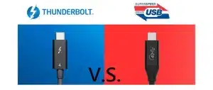
USB-C vs USB 3.0 vs USB4: Which Connector Do You Need for Your Next Design?
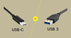
If you’re specifying a USB connector for a new product, you’ve probably run into three overlapping terms: USB-C, USB 3.0, and USB4. They sound like a version progression, but they actually answer three different questions — connector shape, data speed, and protocol capability. Choosing wrong can mean redesigning your PCB six months into production. This … Read more