
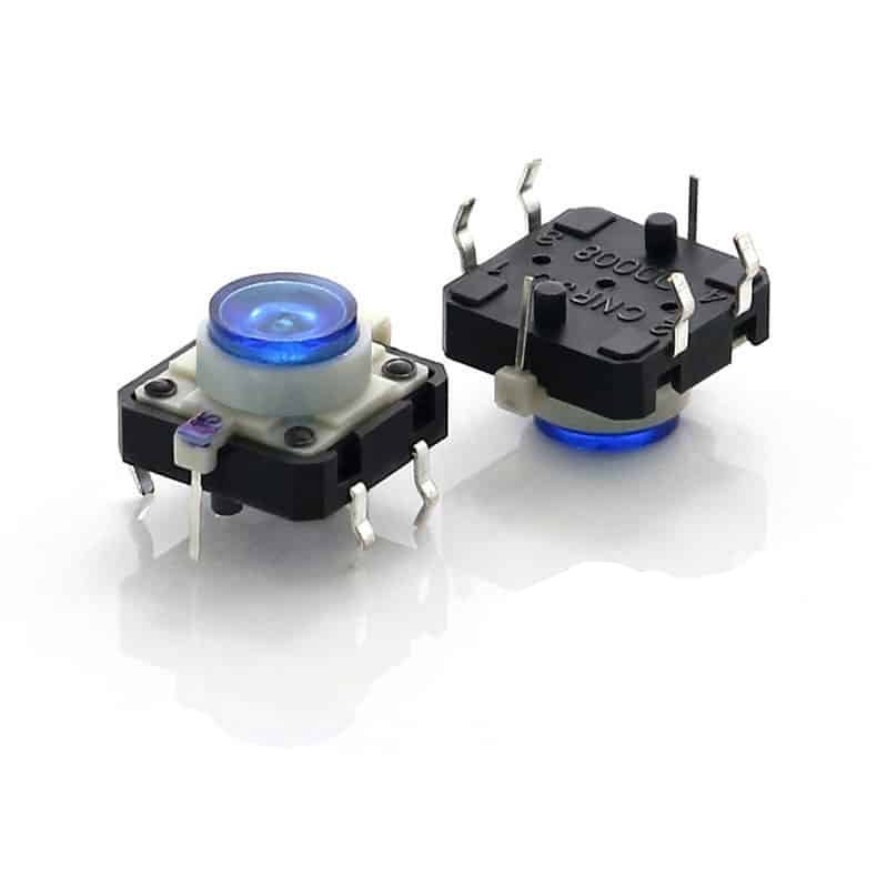
12mm LED Tact Switch for PCB Mounting and HMI Applications
12mm LED Tact Switch — Product Overview
The TS-1103GL is a 12mm LED tact switch engineered for human-machine interface (HMI) applications where visual status indication is as critical as tactile feedback. This illuminated tactile switch integrates a high-brightness LED directly into the 12mm x 12mm package, providing clear visual confirmation of switch state — power ON/OFF, function active, or error condition — without requiring a separate indicator LED on the PCB[reference:0].
As a LED tactile push button switch, the TS-1103GL combines the familiar “click” feedback of a momentary tact switch with an integrated LED that illuminates the actuator. The switch uses a 4-pin DIP through-hole configuration — two pins for the switch contacts (SPST-NO) and two pins for the LED — simplifying PCB layout while maintaining mechanical robustness[reference:1]. Rated at 50mA at 12VDC with a contact resistance of ≤100mΩ and insulation resistance ≥100MΩ at 500VDC[reference:2], this 12mm illuminated tact switch delivers reliable performance across 100,000 electrical cycles[reference:3].
The 12mm footprint is an industry-standard size for illuminated tact switches, offering a balance between actuator surface area (comfortable for finger operation) and PCB space efficiency. The DIP through-hole mounting provides superior mechanical anchoring compared to SMT alternatives, making it the preferred choice for applications subject to vibration or repeated actuation[reference:4].
12mm LED Tact Switch — Full Technical Specifications (TS-1103GL)
| Parameter | Value | Notes |
|---|---|---|
| Part Number | TS-1103GL | Standard catalog item |
| Product Type | Illuminated Tactile Push Button Switch | 12mm x 12mm square |
| Mounting Type | Through-Hole (DIP) | 4-pin configuration |
| Circuit | SPST-NO (Momentary) | Normally open |
| Contact Rating | 50mA @ 12VDC | Low-voltage/logic-level[reference:5] |
| Contact Resistance | ≤ 100mΩ (initial) | After life: ≤ 2Ω[reference:6] |
| Insulation Resistance | ≥ 100MΩ @ 500VDC | High isolation[reference:7] |
| Dielectric Strength | 500VAC for 1 minute | —[reference:8] |
| Travel (Stroke) | 0.25 ± 0.10mm | Short tactile travel[reference:9] |
| Operating Force | 180gf / 260gf | Standard and high-force options[reference:10] |
| Mechanical Life | 100,000 cycles | —[reference:11] |
| Electrical Life | 100,000 cycles | —[reference:12] |
| Operating Temperature | −40°C to +85°C | Industrial grade[reference:13] |
| Storage Temperature | −40°C to +85°C | 60% RH max[reference:14] |
| LED Colors Available | Red, Green, Blue, Yellow | Single-color options[reference:15] |
| Actuator Material | PA66 (UL HB) | —[reference:16] |
| Frame Material | PA66 (UL HB) | Black[reference:17] |
| Contact Material | Stainless Steel with Ag | —[reference:18] |
| Terminal Material | Brass with Ag | —[reference:19] |
| Wave Soldering | 260°C for 10s max | —[reference:20] |
| Hand Soldering | Under 350°C for 3s max | —[reference:21] |
| Compliance | RoHS, REACH | Globally export ready[reference:22] |
| Packaging | ESD Tray / Bag | Production ready[reference:23] |
12mm Illuminated Tact Switch — LED Color Options and Typical Applications
One of the key advantages of the 12mm illuminated tact switch is the ability to choose LED colors that match your product’s design language or indicate specific operational states. The TS-1103GL series is available in four standard single-color options, with dual-color and RGB variants available upon request[reference:24].
| LED Color | Peak Wavelength | Typical Application | Common Use Case |
|---|---|---|---|
| Red | 650nm[reference:25] | Power / Alarm | Indicates device is powered ON or in an error/fault state |
| Green | 574nm[reference:26] | Status / Ready | Indicates normal operation, ready state, or function active |
| Blue | 520nm[reference:27] | Standby / Mode | Indicates standby mode, Bluetooth/Wi-Fi active, or secondary function |
| Yellow | 590nm[reference:28] | Warning / Attention | Indicates caution, attention required, or configuration mode[reference:29] |
For applications requiring more sophisticated visual feedback, dual-color (red/green) and tri-color (red/green/blue — RGB) options are available. These allow a single switch to display multiple states — for example, green for “ready,” yellow for “busy,” and red for “error” — without requiring multiple indicator LEDs[reference:30].
How an Illuminated Tact Switch Works — Internal Architecture and Signal Flow
Understanding how an LED tactile push button switch works is essential for proper integration into your PCB design. The TS-1103GL combines two independent electrical functions within a single 12mm package:
🔘 Switch Circuit (SPST-NO)
- Button Press → Dome Collapses
- Contact Bridge → Closes Circuit
- Signal Path → Pin 1 ↔ Pin 2
- Release → Dome Springs Back → Circuit Opens
💡 LED Circuit (Illumination)
- LED Anode → Connect to +V (via resistor)
- LED Cathode → Connect to GND
- Current Flow → LED Illuminates
- Independent → LED circuit separate from switch
The switch and LED circuits are electrically independent — the LED can be illuminated regardless of whether the switch is pressed. This allows the LED to serve as a continuous status indicator (e.g., “power ON”) or to be controlled separately by a microcontroller for dynamic effects like blinking or dimming via PWM[reference:31].
When the button is pressed, the internal metal dome collapses, bridging the two switch contacts and completing the circuit. Upon release, the dome springs back to its original shape, breaking the circuit. The tactile “click” feedback is generated by the dome’s snap action, providing both audible and physical confirmation of actuation[reference:32].
How to Choose a 12mm LED Tact Switch — 7 Key Selection Criteria
Selecting the right 12mm LED tact switch for your application requires careful consideration of several technical parameters. Here are the seven most important factors to evaluate:
1. LED Color
Red for power/alarm, green for status/ready, blue for standby, yellow for warning. Consider dual-color or RGB for multi-state indication[reference:33].
2. LED Voltage & Current
The TS-1103GL is rated for 12VDC at 50mA. Ensure your drive circuit can supply adequate current and that a current-limiting resistor is used[reference:34].
3. Mounting Style
Through-hole (DIP) provides superior mechanical strength for panel-mounted applications. SMT is available for space-constrained designs[reference:35].
4. Operating Force
180gf (light) for frequent actuation, 260gf (heavy) for applications requiring firmer press feedback to prevent accidental activation[reference:36].
5. Actuator Height
Different actuator heights (e.g., 7.3mm, 8.2mm, 9.5mm) affect the button’s protrusion above the PCB and panel[reference:37].
6. Lifetime (Cycles)
TS-1103GL offers 100,000 cycles. For higher-duty applications, consider switches rated for 500,000 or 1,000,000 cycles[reference:38].
7. Operating Temperature
−40°C to +85°C for industrial applications. For automotive under-hood or outdoor use, verify the temperature range meets your requirements[reference:39].
LED Tact Switch vs Standard Tact Switch — Which One Should You Choose?
One of the most common questions engineers face is whether to use an illuminated tactile switch or a standard (non-illuminated) version. The decision ultimately comes down to a trade-off between user experience and design complexity[reference:40].
| Feature | Standard Tact Switch | LED Tact Switch (Illuminated) |
|---|---|---|
| Primary Feedback | Tactile & Audible (the “click”) | Visual (LED) + Tactile & Audible[reference:41] |
| Visual Indication | None | ON/OFF status, error state, mode selection[reference:42] |
| Pins/Terminals | 2 (SPST) or 4 (stability) | 4-6 total (2 for switch + 2/4 for LED/RGB)[reference:43] |
| PCB Footprint | Smallest, simplest connection | Larger, requires dedicated traces/resistor[reference:44] |
| Power Draw | Negligible (switch contacts) | Higher (requires power for the LED)[reference:45] |
| Cost | Lowest per unit | Higher (switch + LED + driver circuit)[reference:46] |
| Life Cycle | High (often 100K to 1M+ cycles) | Limited by both switch and LED lifespan[reference:47] |
| Best For | Battery-powered, low-cost, internal/unseen functions | High-visibility interfaces, control panels, safety devices[reference:48] |
Choose an LED tact switch DIP when:
- User needs visual confirmation of switch state (especially in low-light environments)
- Status indication (power ON, function active, error) is critical for safe operation
- Product aesthetics and UI design call for illuminated controls
Choose a standard tact switch when:
- Power consumption is a primary concern (battery-powered devices)
- Cost is the dominant factor
- The switch is used for internal functions where visual feedback isn’t required
12mm LED Tact Switch Applications — Industrial HMI, Medical, Automotive & More
Machine control interfaces, operator panels, and factory automation equipment[reference:49]
Patient monitors, diagnostic equipment, and laboratory instruments[reference:50]
Custom keyboards, macro pads, and arcade-style control panels
Payment terminals, barcode scanners, and retail checkout systems
Studio monitors, mixing consoles, and professional audio interfaces[reference:51]
Climate controls, infotainment systems, and steering wheel buttons[reference:52]
Smart home interfaces, coffee machines, and white goods
Thermostats, lighting controls, and home automation gateways
PCB Design Recommendations for 12mm LED Tact Switch — Footprint, Routing & Soldering
Proper PCB design is essential for reliable operation of your LED tact switch DIP. Here are key recommendations for footprint design, routing, and assembly:
📐 Footprint (Land Pattern)
- Pin Pitch: Standard DIP pitch — typically 5.0mm x 5.0mm or 6.5mm x 4.5mm between the two switch pins[reference:53]
- Hole Diameter: 0.8mm to 1.0mm for through-hole pins (allow 0.2mm clearance)
- Pad Diameter: 1.2mm to 1.5mm for reliable solder joint formation
- Keep-out Area: Maintain 0.5mm clearance around the switch body for automated assembly
🔌 Routing Guidelines
- Switch Pins: Route as standard signal traces — no special impedance requirements
- LED Pins: Pay attention to polarity — the anode (+) and cathode (−) must be correctly identified[reference:54]
- Current-Limiting Resistor: Place a series resistor (typically 220Ω to 1kΩ, depending on LED color and desired brightness) close to the LED anode[reference:55]
- LED Drive: For PWM dimming, connect the LED anode to a microcontroller PWM pin[reference:56]
♨️ Soldering Recommendations
- Wave Soldering: Maximum 260°C for 10 seconds[reference:57]
- Hand Soldering: Under 350°C for 3 seconds maximum[reference:58]
- Flux: Use no-clean or water-soluble flux compatible with the switch materials
- Cleaning: Avoid aggressive solvents that may damage the LED or actuator
7 Common Mistakes When Using an Illuminated Tact Switch — and How to Avoid Them
Even experienced engineers can make mistakes when integrating an illuminated tactile switch into their design. Here are the seven most common errors and how to avoid them:
❌ 1. Forgetting the External LED Resistor
The switch does not have a built-in current-limiting resistor[reference:59]. Without it, the LED will draw excessive current and fail prematurely.
❌ 2. Reversing LED Polarity
LEDs are polarity-sensitive. Reversing anode and cathode won’t damage the LED (up to 5V reverse) but it simply won’t light up[reference:60].
❌ 3. Choosing the Wrong LED Voltage
Different LED colors have different forward voltages (red ~2.0V, green/blue ~3.0-3.5V). Design your drive circuit accordingly.
❌ 4. Incorrect PCB Hole Size
Holes that are too small can damage pins during insertion; holes that are too large compromise solder joint strength.
❌ 5. Using a Low-Life Switch in High-Duty Applications
If your application requires frequent actuation, choose a switch rated for 500,000+ cycles, not the standard 100,000-cycle version.
❌ 6. Overlooking ESD Protection
The switch contains sensitive LED components. Handle with ESD precautions and consider ESD protection diodes in your circuit[reference:61].
❌ 7. Ignoring the Switch’s Symmetrical Layout
The 12mm tact switch pinout is symmetrical — you can rotate it 180° to correct LED polarity without affecting the switch function[reference:62].
12mm LED Tact Switch — Frequently Asked Questions
What is a 12mm LED tact switch?
A 12mm LED tact switch is an illuminated tactile push button switch with a 12mm x 12mm square footprint. It combines a momentary SPST-NO switch with an integrated LED for visual status indication. The TS-1103GL is a DIP through-hole version rated at 50mA at 12VDC with up to 100,000 cycles.
Does the LED require an external current-limiting resistor?
Yes. The TS-1103GL and most LED tact switch DIP products do not have built-in current-limiting resistors[reference:63]. You must add an external series resistor (typically 220Ω to 1kΩ) between the LED anode and the power supply to limit current and prevent LED damage. The exact resistor value depends on the LED color, forward voltage, and desired brightness.
Can the LED and switch be wired separately?
Yes. The switch contacts and LED are electrically independent. The two switch pins (pins 1 and 2) form the momentary SPST-NO circuit, while the two LED pins (anode and cathode) form the illumination circuit. This allows you to control the LED independently of the switch state — for example, keeping the LED illuminated continuously as a power indicator, or driving it with a PWM signal for dimming[reference:64].
What LED colors are available?
The TS-1103GL series is available in red, green, blue, and yellow single-color options[reference:65]. Dual-color (red/green) and tri-color (red/green/blue — RGB) variants are also available upon request[reference:66]. Each color has a specific peak wavelength: red (650nm), green (574nm), blue (520nm), and yellow (590nm)[reference:67].
Is it momentary or latching?
The TS-1103GL is a momentary (non-latching) switch. The circuit is closed only while the button is pressed. When released, the internal dome springs back and the circuit opens. It is a SPST-NO (Single Pole Single Throw — Normally Open) configuration[reference:68].
What is the operating life (cycles)?
The TS-1103GL is rated for 100,000 mechanical and electrical cycles[reference:69]. For higher-duty applications, Vistar offers variants with 500,000 or 1,000,000 cycle ratings. Contact our sales team for specific requirements.
Can it be customized?
Yes. Vistar Electronics offers customization options for the TS-1103GL series, including custom LED colors, actuator colors and shapes, operating force (180gf or 260gf), actuator height, and custom branding. Minimum order quantities apply for custom variants. Contact sales@vistarelectronics.com for details.
Is it RoHS compliant?
Yes. The TS-1103GL is fully RoHS and REACH compliant[reference:70], making it suitable for export to North America, Europe, and Asia without regulatory complications.
What is the MOQ and can I get free samples?
Standard MOQ is 1,000 pieces with a 2–4 week production lead time. Free samples are available for qualified engineering and product development projects. Contact sales@vistarelectronics.com with your company details, project application, and part number (TS-1103GL), or click the “Request a Quote” button at the top of this page[reference:71].
What is the difference between the TS-1103GL and other 12mm tact switches?
The TS-1103GL is a 12mm LED tact switch with a 4-pin DIP through-hole configuration, 180gf/260gf operating force options, and 100,000-cycle life. Key differentiators include the integrated LED with multiple color options, wide operating temperature range (−40°C to +85°C), and RoHS/REACH compliance. It is compatible with standard 12mm tact switch footprints and is a drop-in replacement for many industry-standard illuminated tact switches[reference:72].
Technical Resources & Industry References
- Würth Elektronik WS-TATL THT Illuminated Tact Switches — DigiKey Product Highlight — Industry reference for 12mm illuminated tact switches[reference:73]
- Illuminated vs Standard Tact Switch: A Definitive Guide for Designers and Engineers — Comprehensive comparison and selection guide[reference:74]
- CIT Relay & Switch JS Series Illuminated Tactile Switch — Alternative 12mm illuminated switch reference[reference:75]

5‑Pin SMD Tactile Switch with Ground Pin – 6.2×6.2mm ESD‑Safe Momentary Push Button for Compact PCB Designs

6×6mm SMD Tactile Switch with Bracket — 4 Pin Momentary Push Button for PCB Mount & SMT Assembly

6mm Waterproof Tact Switch SMD 4Pin – IP67 Sealed Tactile Switch

6×6 Waterproof Tactile Switch – IP67 4 Pin DIP Momentary Switch

Momentary tactile switch 3*5

4 Pin SMD Tact Switch 6.2×6.2mm (TS-1158) for Compact PCB Keypads and Control Panels

6X6 Tact switch waterproof snap-in type

Compact 3×6 mm SMD Tactile Switch for Space‑Constrained PCBs

Waterproof Tactile Switch Guide: Everything You Need to Know
Introduction Learn everything about waterproof tactile switch guide, including IP67 protection, sealing technologies, switch types, testing standards, applications, and expert tips for...

Tactile Switch Selection Guide: How to Choose the Right Switch for Your Application
Master tactile switch selection with this engineering guide. Learn sizing, mounting, IP ratings, operating force, and avoid common sourcing mistakes. Read now....

Tactile Switch Types: 7 Options Engineers Should Know
A design team once finished the entire PCB layout for a handheld diagnostic tool, only to discover that the selected tactile switch...