
Learn how to choose the right USB-C 24 pin connector for USB4, USB 3.2 and Power Delivery applications. Compare mounting styles, PCB layout, pin configurations and engineering considerations.
You have just finished the schematic. The PCB layout is fifty percent routed. Then you realize the USB-C connector you specified is out of stock — or worse, it does not actually support the data rate your processor requires. The 24-pin part you picked from a parametric search turns out to be a 16-pin variant with the same footprint, and now you are facing a respin.
This scenario plays out in engineering labs more often than most procurement teams would admit. The USB-C 24 pin connector looks simple on paper: twenty-four contacts, reversible, handles power and data. But beneath that symmetrical exterior lies a component with enough variation in signal integrity, mechanical durability, and thermal performance to derail an otherwise solid design.
This guide walks through what actually matters when selecting a 24-pin USB-C receptacle — not the marketing fluff, but the engineering decisions that determine whether your port survives 10,000 mating cycles and passes USB-IF compliance on the first attempt.
Why 24 Pins? Understanding What You Are Actually Getting
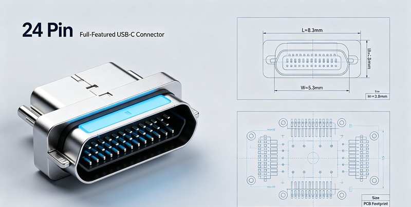
The USB Type-C specification defines a 24-pin receptacle with two mirrored rows of twelve contacts each. But not every USB-C port uses all twenty-four pins. A 6-pin connector delivers power only. A 16-pin variant adds USB 2.0 data but drops the SuperSpeed differential pairs required for USB 3.x and USB4.
The 24-pin full-featured configuration is the only variant that supports the complete USB-C ecosystem:
- Four SuperSpeed differential pairs (TX1/RX1, TX2/RX2) enabling USB 3.2 Gen 2×2 (20 Gbps) and USB4 (40 Gbps)
- USB 2.0 D+/D- pair for backward compatibility
- CC1 and CC2 pins for orientation detection and Power Delivery negotiation
- SBU1 and SBU2 sideband pins for Alternate Mode support (DisplayPort, HDMI, Thunderbolt)
- Dedicated VBUS and GND contacts rated for 5A continuous current
If your application requires video output, 10 Gbps or faster data, or 100W+ Power Delivery, the 24-pin connector is not optional — it is the minimum viable configuration.
9 Critical Selection Factors for USB-C 24 Pin Connectors
1. USB Standard Support: 10 Gbps vs. 20 Gbps vs. 40 Gbps
A 24-pin connector provides the physical pins for high-speed data, but the connector itself must be designed and tested for the target data rate. Not all 24-pin receptacles are created equal.
For USB 3.2 Gen 1 (5 Gbps), most 24-pin connectors will perform adequately. For USB 3.2 Gen 2 (10 Gbps), the connector must maintain controlled impedance (90Ω ±10% differential) and minimize crosstalk between adjacent differential pairs. For USB4 Gen 3 (40 Gbps), the connector must pass signal integrity testing — a requirement that did not exist for earlier USB generations.
The USB Type-C Specification Revision 2.4, released in October 2024, added a 12.8 GHz test frequency to the insertion loss test for USB4 Gen 3 and Gen 4 cable assemblies. Connectors that passed older revisions may not meet the new requirements.
Engineering tip: If your datasheet does not explicitly state USB4 or 40 Gbps support, assume the connector is limited to 10 Gbps or lower. Verify the connector manufacturer has performed the signal integrity testing required for USB4 certification.
2. Current Rating and Power Delivery Capability
The USB Power Delivery specification supports up to 240W (48V at 5A). But the connector itself must be rated for that current.
Most 24-pin USB-C receptacles are rated for 5A on the VBUS and GND contacts. However, the current rating alone does not tell the full story. The contact resistance determines how much heat the connector generates under load. A connector with 40 mΩ contact resistance dissipates 1W of heat at 5A — enough to cause reliability issues in a tightly packed enclosure.
Look for connectors that specify:
- Contact resistance (≤40 mΩ initial, preferably lower)
- Temperature rise under rated current (typically ≤30°C above ambient)
- Operating temperature range (-30°C to +85°C is common for commercial grades)
Engineering tip: For 240W PD applications, prioritize connectors with four shell stakes for improved heat dissipation and mechanical retention. The additional metal mass helps conduct heat away from the contacts.
3. Mounting Style: Top-Mount, Mid-Mount, Right-Angle, or Vertical
The mounting style determines how the connector integrates with your PCB and enclosure. Each configuration has distinct trade-offs:
| Mounting Style | Best Application | Key Trade-off |
|---|---|---|
| Top-Mount SMT | Standard PCB designs, high-volume production | Easiest assembly, but tallest profile |
| Mid-Mount (Sinking) | Ultra-thin laptops, tablets, handheld devices | Reduces overall height by recessing into PCB |
| Right-Angle SMT | Edge-mount applications, docking stations | Saves vertical space, requires PCB edge placement |
| Vertical SMT | Top-panel ports, industrial equipment | Mating face perpendicular to PCB |
| DIP Through-Hole | High-reliability, industrial, automotive | Strongest mechanical retention, but higher assembly cost |
| Hybrid (SMT + DIP) | Applications needing both automated assembly and mechanical strength | Combines SMT signal pins with through-hole retention tabs |
Mid-mount connectors are particularly valuable for slim devices. By allowing the connector body to sit partially below the PCB surface, they reduce the mounted height by 0.5mm to 1.0mm compared to top-mount variants. The trade-off is increased PCB fabrication complexity — the board requires a cutout with precise dimensions.
Engineering tip: Match the mounting style to your PCB thickness specification. Mid-mount connectors are typically designed for specific board thicknesses (0.8mm, 1.0mm, or 1.2mm). Using the wrong thickness results in poor solder joint formation or mechanical misalignment.
4. PCB Thickness Compatibility
This factor is deceptively simple and frequently overlooked. The connector’s PCB thickness specification defines the board thickness range the connector is designed to mate with — particularly critical for mid-mount and sinking connectors.
If your PCB thickness does not match the connector’s specification:
- The connector may not sit flush with the board surface
- Solder joints may be stressed or incomplete
- The connector may not align with the enclosure opening
Mid-mount connectors are typically specified for 0.8mm, 1.0mm, or 1.2mm PCBs. Verify this specification before finalizing your board stack-up.
5. Mating Cycle Rating: 5,000 vs. 10,000 vs. 20,000
Mating cycle rating defines how many times the connector can be plugged and unplugged before electrical or mechanical degradation occurs.
The USB-C specification requires 10,000 mating cycles for standard connectors. This is the baseline for consumer electronics — laptops, tablets, smartphones. Industrial and medical applications may require 20,000 cycles or higher.
The mating cycle rating depends on:
- Contact plating thickness (30µ” gold provides significantly better wear resistance than flash gold)
- Shell design (double-shell connectors offer better mechanical stability)
- Contact spring design (BeCu or phosphor bronze with appropriate stress relief)
Engineering tip: For devices that experience frequent connection and disconnection — test equipment, medical monitors, industrial HMIs — specify 20,000 cycles or higher. The cost premium is minimal compared to field failures.
6. Contact Plating: Flash Gold vs. 30µ” Gold
Contact plating directly affects electrical performance, mechanical durability, and corrosion resistance.
| Plating Type | Thickness | Characteristics | Best For |
|---|---|---|---|
| Gold Flash | 0.8–1.0 µm | Lower cost, adequate for occasional mating | Cost-sensitive consumer devices |
| 30µ” Gold | 0.75 µm (30 micro-inches) | Superior wear resistance, stable contact resistance | High-reliability, industrial, premium applications |
Thicker gold plating maintains lower and more stable contact resistance over the connector’s lifetime. It also provides better corrosion protection in humid or harsh environments.
Engineering tip: For applications requiring frequent mating cycles or operating in challenging environments, specify 30µ” gold plating. The additional cost is negligible compared to the reliability benefits over the product’s lifecycle.
7. Shell Design: Single Shell vs. Double Shell
The connector shell is not just mechanical protection — it is a critical component of EMI shielding.
- Single shell: Basic shielding, lower cost, adequate for USB 2.0 and lower-speed USB 3.x applications
- Double shell: Enhanced shielding, superior EMI performance, essential for USB4 and Thunderbolt
For high-speed applications (USB4, 40 Gbps), double-shell connectors provide the EMI suppression required to pass certification. The metal shell must be firmly connected to PCB ground through multiple low-inductance paths — stitching vias and grounding clips placed around the connector footprint.
Engineering tip: For USB4 designs, choose double-shell connectors and ensure the shell is grounded with multiple vias around the connector footprint. Maintain a 1–2mm gap between the shell ground and other ground planes to control return currents.
8. Housing Material: LCP vs. PA9T vs. Standard Nylon
The connector housing material determines thermal performance, mechanical strength, and manufacturing reliability.
| Material | Characteristics | Reflow Compatibility |
|---|---|---|
| LCP (Liquid Crystal Polymer) | High heat resistance, excellent dimensional stability, UL94 V-0 | 260°C reflow compatible |
| PA9T (Nylon 9T) | High heat resistance, good mechanical properties | 260°C reflow compatible |
| Standard Nylon | Lower cost, lower heat resistance | May deform at peak reflow temperatures |
For SMT assembly, the housing must withstand peak reflow temperatures (typically 260°C) without deforming. LCP is the preferred material for its thermal stability and low moisture absorption.
Engineering tip: Check the connector’s moisture sensitivity level (MSL). Some materials absorb moisture and can “popcorn” during reflow if not properly baked before assembly.
9. Assembly Method: SMT, DIP, or Hybrid
The assembly method affects manufacturing cost, reliability, and PCB design complexity:
| Assembly Method | Advantages | Considerations |
|---|---|---|
| SMT | Automated assembly, lower cost, high-volume production | Requires precise solder paste printing, lower mechanical strength |
| DIP Through-Hole | Stronger mechanical retention | Requires wave soldering or hand soldering, higher cost |
| Hybrid (SMT + DIP) | Best of both worlds — automated signal pins with through-hole retention | More complex assembly, but excellent reliability |
For high-volume consumer electronics, SMT is the standard — connectors are supplied in tape-and-reel packaging for automated pick-and-place assembly. For industrial or automotive applications where mechanical robustness is paramount, hybrid or DIP mounting is preferred.
Engineering tip: Consider the PCB assembly flow early in the design phase. SMT connectors go through the same reflow oven as other SMT components. Through-hole connectors require a separate soldering step, increasing cost and cycle time.
PCB Layout Considerations for USB-C 24 Pin Connectors
Once you have selected the connector, the PCB layout determines whether the design meets signal integrity requirements and passes compliance testing.
Placement Guidelines
Position the USB-C connector at the PCB edge, typically 3–5mm from the board edge to facilitate plug insertion. Leave at least 2.5mm of clear space in front of the connector — no components in this area — for mechanical clearance.
Signal Integrity for High-Speed Lanes
The 24-pin USB-C connector includes four SuperSpeed differential pairs that must be routed with care:
- Route differential pairs with 90Ω impedance (±10%)
- Match differential pair lengths within 5 mils (0.127mm) to avoid timing skew
- Use no more than 2 vias per differential pair
- Use 45° bends instead of 90° corners to reduce signal reflection
- Maintain a continuous ground plane beneath all high-speed signals
ESD Protection Placement
Place ESD protection devices in the following order, starting from the connector:
Connector → TVS/ESD (closest) → Common-mode choke → Series capacitors → IC
For high-speed lanes (SuperSpeed differential pairs), use ultra-low capacitance TVS diodes (<0.5pF) to avoid degrading signal integrity.
Power Routing
VBUS and GND traces must handle the required current:
- For 3A: minimum trace width of 20 mils (adjust based on copper weight)
- For 5A: scale width accordingly — typically 50 mils or wider
- Place bulk capacitors (e.g., 100µF) and ceramic bypass capacitors (0.1µF) close to the connector
CC Pin Routing
CC1 and CC2 are critical for orientation detection and PD communication. Route them directly to the CC logic or PD controller. Place 5.1kΩ pull-down resistors close to the connector. Consider TVS protection on these lines as well.
Common Design Mistakes to Avoid
Mistake #1: Specifying a 16-Pin Connector When You Need USB4
A 16-pin connector physically fits in the same footprint but lacks the SuperSpeed differential pairs required for USB4 or Thunderbolt. The device will work — at USB 2.0 speeds — but the customer will wonder why their “USB-C” port is so slow.
Fix: Always verify the pin count matches your data speed requirements before finalizing the BOM. If your processor supports USB4, you need a 24-pin connector.
Mistake #2: Inadequate Shell Grounding
Floating or poorly grounded shells create EMI issues that can cause USB certification failures. High-speed signals radiate from the connector body if the shell is not properly grounded.
Fix: Connect the metal shell to chassis ground through multiple vias placed around the connector footprint.
Mistake #3: Copying the Wrong Footprint
Using a footprint from a different manufacturer or an outdated version leads to solder joint failures or mechanical misalignment. Even connectors with the same pin count can have different pad dimensions.
Fix: Always download the latest footprint from your specific connector vendor and double-check the dimensions against your PCB CAD library.
Mistake #4: Height Mismatch with Enclosure
The connector’s profile height must match the enclosure opening. A connector that is too tall protrudes; one that is too short does not align with the port opening.
Fix: Verify the connector height specification against your mechanical CAD model before ordering samples. Mid-mount connectors can help reduce height in thin devices.
Mistake #5: Ignoring PCB Thickness for Mid-Mount Connectors
Mid-mount connectors are designed for specific PCB thicknesses. Using a 1.0mm connector on a 0.8mm board results in poor solder joint formation.
Fix: Match the connector’s PCB thickness specification to your actual board stack-up.
Which USB-C 24 Pin Connector Fits Your Product?
| Product Type | Recommended Mounting | Key Requirements |
|---|---|---|
| Laptop / Ultrabook | Mid-Mount (Sinking) | Minimizes overall device height |
| Docking Station | Right-Angle SMT | Edge-mount, saves vertical space |
| Tablet | Mid-Mount or Vertical | Depends on port location and enclosure design |
| Industrial PC | DIP Through-Hole or Hybrid | Maximum mechanical reliability |
| POS Terminal | Right-Angle or Vertical | Depends on mounting orientation |
| AI Edge Box | Right-Angle SMT | USB4/40 Gbps support required |
| Medical Device | DIP or Hybrid | High reliability, 20,000+ mating cycles |
| Consumer Peripheral | Top-Mount SMT | Cost-effective, high-volume production |
Frequently Asked Questions
Does every 24-pin connector support USB4?
No. The 24-pin configuration provides the physical pins for high-speed data, but the connector must be designed and tested for USB4 operation (40 Gbps). Some 24-pin connectors are only rated for USB 3.2 Gen 1 (5 Gbps) or Gen 2 (10 Gbps). Always check the datasheet.
Can a 24-pin connector support 240W PD?
Yes, but not all of them. Look for connectors explicitly rated for 5A continuous current and 48V operation. The connector must also have adequate thermal management to handle the heat generated at 240W.
How many insertion cycles should I specify?
For consumer devices: 10,000 cycles is standard. For industrial, medical, or test equipment: specify 20,000 cycles or higher.
How do I choose between single shell and double shell?
Double shell provides superior EMI shielding and is recommended for USB4, Thunderbolt, and other high-speed applications. Single shell is adequate for lower-speed designs.
What is the recommended PCB thickness for mid-mount connectors?
Mid-mount connectors are typically designed for specific PCB thicknesses such as 0.8mm, 1.0mm, or 1.2mm. Verify the connector’s specification against your board stack-up before finalizing the design.
Putting It All Together
Selecting a USB-C 24 pin connector is not a one-size-fits-all decision. The choice depends on your data rate requirements, power delivery needs, mechanical constraints, assembly process, and target reliability.
Start with the pin count — if you need USB4, Thunderbolt, or DisplayPort Alt Mode, you need 24 pins. Then evaluate the nine factors covered in this guide: USB standard support, current rating, mounting style, PCB thickness compatibility, mating cycle rating, contact plating, shell design, housing material, and assembly method.
The PCB layout considerations — placement, signal integrity, ESD protection, and power routing — are equally critical. A well-selected connector paired with a poorly executed layout will fail compliance testing every time.
For engineers designing next-generation products, the 24-pin USB-C connector is not just a port — it is the central I/O hub of the device. Choose carefully, and your design will pass USB-IF compliance on the first attempt. Choose poorly, and you will be respinning the board.
This guide is part of Vistar Electronics’ technical resource library for engineers designing with USB-C connectors. For product specifications, samples, or engineering support, visit our USB-C Receptacle product page or explore our 24-pin USB-C connector selection.
Additional engineering resources: USB-C connector pinout guide, mid-mount right-angle connector solutions, and the USB-IF Type-C Cable and Connector Specification.


