

RJ45 SMT Connector 8P8C Single Port — Shielded RJ45 Modular Jack for 10/100/1000BASE-T Ethernet Networking, Industrial Control & Embedded Systems
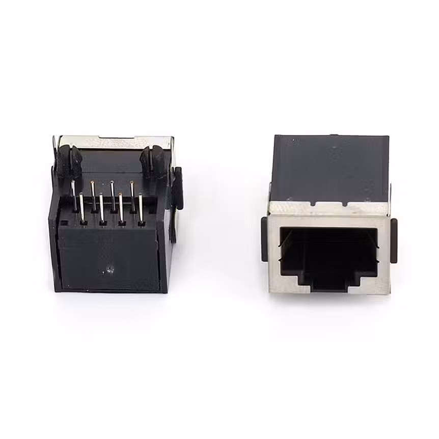
The RJ45-1X03 is an RJ45 SMT connector featuring a single-port 8P8C configuration with fully shielded metal housing. Rated 1.5A at 125VAC with 30N maximum insertion and withdrawal force.
RJ45 SMT Connector 8P8C Single Port — Product Overview
The RJ45-1X03 is an RJ45 SMT connector engineered for modern Ethernet communication systems where reliable network connectivity must be delivered in a compact, surface-mountable package. The 8P8C (8 Position, 8 Contact) configuration is the universal standard for twisted-pair Ethernet cabling, ensuring immediate compatibility with Cat5e, Cat6, and Cat6a patch cables used in LAN, WAN, and industrial network installations worldwide.
Unlike through-hole RJ45 jacks that require drilled holes and secondary wave soldering operations, this RJ45 female connector SMT configuration solders directly to surface pads using standard reflow profiles. The surface-mount approach eliminates the need for additional assembly steps, reduces PCB layer transitions, and enables denser component placement on the opposite board face — critical for compact networking equipment, embedded systems, and IoT devices where every square millimeter of PCB real estate is contested.
The fully shielded metal housing provides 360-degree EMI protection, containing radiated emissions from high-speed differential pairs and preventing external electromagnetic interference from degrading signal integrity. This shielding is essential for Gigabit Ethernet (1000BASE-T) applications where signal frequencies reach 125 MHz per pair and even minor EMI coupling can cause packet loss, retransmissions, and throughput degradation. The shield is electrically connected to PCB ground through multiple solder tabs, ensuring low-impedance grounding and effective noise suppression across the full operating frequency range.
With support for 10/100/1000BASE-T Ethernet standards, this single port RJ45 connector serves applications from legacy 10 Mbps industrial networks to modern Gigabit enterprise infrastructure. The 1.5A current rating per contact provides headroom for Power over Ethernet (PoE) applications when combined with appropriate magnetics and power delivery circuitry, enabling single-cable solutions for IP cameras, wireless access points, and VoIP phones.
RJ45 Modular Jack SMT — Full Technical Specifications
| Parameter | Value | Notes |
|---|---|---|
| Part Number | RJ45-1X03 | Standard catalog item |
| Product Type | RJ45 SMT Connector | Single-port 8P8C modular jack |
| Connector Standard | RJ45 (IEC 60603-7) | Universal Ethernet interface |
| Port Configuration | Single Port | One 8P8C jack position |
| Pin Configuration | 8P8C | 8 positions, 8 contacts |
| Mounting Type | SMT (Surface Mount Technology) | Reflow solder compatible |
| Shield Type | Fully Shielded (Metal Housing) | 360° EMI protection |
| Ethernet Standard | 10/100/1000BASE-T | 10 Mbps to 1 Gbps support |
| Current Rating | 1.5A per contact | Supports signal and PoE applications |
| Voltage Rating | 125VAC | Standard telecom voltage rating |
| Insertion Force | ≤ 30N | Maximum per IEC 60603-7 |
| Withdrawal Force | ≤ 30N | Maximum per IEC 60603-7 |
| Contact Resistance | ≤ 20 mΩ | Initial value at rated current |
| Insulation Resistance | ≥ 500 MΩ | At 500V DC |
| Dielectric Strength | 1,000V AC / 1 minute | No breakdown or flashover |
| Contact Material | Phosphor Bronze | Excellent spring properties |
| Contact Plating | Gold over Nickel | 50 μ” gold typical for reliability |
| Shield Material | Stamped Steel, Nickel Plated | Corrosion resistant, solderable |
| Insulator Material | High-Temperature Thermoplastic | UL94V-0, reflow compatible |
| Operating Temperature | −40°C to +85°C | Commercial and industrial grade |
| Storage Temperature | −40°C to +85°C | Long-term storage conditions |
| Reflow Soldering | Compatible | Peak 260°C, lead-free compatible |
| Packaging | Bag / Tray | Tape & reel available for volume |
| Compliance | RoHS 3 & REACH | Global export compliant |
Why Engineers Choose the RJ45 Female Connector SMT for High-Performance Ethernet Designs
Fully Shielded Metal Housing — Superior EMI/RFI Protection
The stamped steel shield with nickel plating provides 360-degree electromagnetic interference protection, essential for maintaining signal integrity in 1000BASE-T Gigabit Ethernet applications. The shield is grounded to the PCB through multiple solder tabs, creating a Faraday cage around the contact area that prevents crosstalk between adjacent connectors and suppresses radiated emissions that could fail FCC/CE certification testing.
SMT Surface Mount — Automated Assembly & PCB Space Optimization
The RJ45 female connector SMT configuration enables single-pass reflow assembly alongside other surface-mount components, eliminating the need for secondary wave soldering operations. This reduces manufacturing cycle time, lowers labor costs, and improves production yield. The SMT footprint leaves the opposite PCB face free for additional components, heat sinks, or shielding — critical for dense networking equipment and multi-port switch designs.
1.5A 125VAC Rating — Signal and PoE Power Delivery
The 1.5A per contact rating supports not only standard Ethernet data signals but also Power over Ethernet (PoE, PoE+, and PoE++) applications when combined with appropriate magnetics. Deliver up to 15.4W (802.3af), 30W (802.3at), or 90W (802.3bt) over a single Cat5e/Cat6 cable to power IP cameras, wireless access points, VoIP phones, and IoT sensors without separate power wiring.
8P8C Universal Compatibility — Standard Ethernet Cable Ecosystem
The 8P8C Ethernet connector PCB mount follows the IEC 60603-7 standard, ensuring compatibility with billions of installed RJ45 patch cables, couplers, keystone jacks, and test equipment worldwide. No custom cables, proprietary adapters, or specialized tooling required — engineers can leverage the entire Ethernet infrastructure ecosystem from day one.
Positive Latch Retention — Secure Cable Connection
The standard RJ45 latch mechanism provides audible and tactile confirmation of proper mating, preventing accidental disconnection from cable tension, vibration, or thermal cycling. The 30N maximum withdrawal force ensures cables remain securely seated while allowing reasonable extraction effort for field service and maintenance operations.
RoHS 3 & REACH Compliant — Global Market Ready
Fully compliant with EU RoHS 3 Directive (2015/863) and REACH SVHC regulations. The lead-free solder-compatible plating and halogen-free insulator materials meet environmental requirements for European, North American, and Asian markets. Full material composition documentation and conflict minerals reporting available for customer audits and regulatory submissions.
Where to Use the Single Port RJ45 Connector — Applications for Networking, Industrial, IoT & Communication
LAN ports on enterprise routers, managed switches, unmanaged switches, and PoE injectors where single-port or multi-port RJ45 configurations provide wired network connectivity for offices, data centers, and industrial facilities.
PROFINET, EtherNet/IP, and Modbus TCP interfaces on PLCs, industrial Ethernet switches, motor drives, and sensor modules where rugged shielded connectors and extended temperature ratings ensure reliable factory floor communication.
Ethernet backhaul connections on smart home hubs, industrial IoT gateways, environmental monitoring stations, and edge computing nodes where compact SMT assembly and single-cable PoE power simplify deployment.
Network interfaces on ARM-based embedded boards, industrial PCs, kiosk controllers, and digital signage players where the SMT RJ45 jack enables automated assembly and minimal PCB footprint.
Network video recorder (NVR) ports, IP camera Ethernet connections, access control panel interfaces, and intercom system networking where PoE support eliminates separate power cabling infrastructure.
Network ports on patient monitors, medical imaging equipment, telehealth terminals, and healthcare IoT devices where shielded connectors prevent EMI interference with sensitive diagnostic signals and comply with IEC 60601 EMC requirements.
RJ45-1X03 PCB Layout, SMT Assembly & Ethernet Signal Integrity Guidelines
Proper PCB design is critical to achieving full Gigabit Ethernet performance from this RJ45 SMT connector. Follow these engineering best practices for high-speed networking applications:
Footprint & Pad Design
- Use the manufacturer-recommended land pattern. The 8P8C SMT footprint requires precise pad sizing, spacing, and shield tab placement to ensure proper solder joint formation and EMI shield grounding. Verify the footprint against the official datasheet before PCB fabrication.
- Implement multiple shield ground tabs. The metal shield should connect to PCB ground through at least 4–6 solder tabs distributed around the connector perimeter. This ensures low-impedance shield grounding and prevents ground bounce that could radiate EMI.
- Maintain adequate solder mask clearance around signal pads and shield tabs to prevent bridging during reflow. Fine-pitch SMT RJ45 connectors require careful solder paste stencil design (typically 1:1 or slightly reduced aperture).
- Include polarization markings on the PCB silkscreen to indicate pin 1 (TX+ / pair 1 positive) orientation, preventing magnetics wiring errors that would cause link failure or crosstalk issues.
Ethernet Signal Integrity & Routing
- Route differential pairs with controlled impedance. 1000BASE-T requires 100Ω ± 10% differential impedance for all four twisted pairs (Pairs 1–4). Maintain consistent trace width, spacing, and layer stackup to achieve target impedance. Use PCB field solvers (Polar, HyperLynx) to verify before fabrication.
- Minimize pair-to-pair skew. All four pairs must arrive at the receiver within ±4 ns skew tolerance for 1000BASE-T. Match trace lengths within each pair to ±0.15 mm and between pairs to ±1.5 mm.
- Implement proper via stitching. Minimize via count on high-speed differential pairs. When vias are unavoidable, use symmetric via pairs with ground return vias placed within 1 mm to maintain return path continuity and reduce stub effects.
- Keep traces away from board edges and split planes. Route differential pairs at least 3× trace width from board edges and avoid crossing split ground or power planes. Reference all pairs to a solid, uninterrupted ground plane for consistent impedance and minimal crosstalk.
- Magnetics placement: Place the Ethernet magnetics (transformer/PHY interface) as close to the RJ45 connector as possible — ideally within 25 mm. This minimizes unbalanced stub length, reduces EMI radiation, and improves common-mode noise rejection.
PoE Power Delivery Considerations
- Current capacity: For PoE applications, ensure PCB traces from the RJ45 connector to the magnetics and power extraction circuitry can handle the required current (up to 600 mA per pair for 802.3bt Type 4). Use 1 oz copper with adequate trace width or 2 oz copper for high-current PoE++ designs.
- Thermal management: PoE power dissipation in the magnetics and rectifier diodes can raise local PCB temperatures. Provide thermal vias, copper pours, and adequate airflow around the RJ45 and magnetics area.
- Isolation: Maintain 1500V AC isolation between PoE power circuits and SELV (Safety Extra-Low Voltage) circuits per IEEE 802.3 and IEC 60950-1 requirements.
Reflow Soldering Profile
- Peak temperature: 245–260°C (verify insulator specification for exact limit)
- Preheat: 150–180°C for 60–120 seconds
- Soak zone: 180–220°C for 60–90 seconds
- Ramp rate: ≤ 3°C/second
- Cooling: Controlled cooling at ≤ 4°C/second
For the official mechanical drawing, recommended PCB land pattern, 3D STEP model, and signal integrity application notes, please contact our sales team or request the RJ45-1X03 datasheet.
Quality Assurance, Ethernet Compliance & Manufacturing Standards
All Vistar RJ45 modular jacks, including this RJ45 SMT connector, are manufactured under stringent quality management systems with networking-specific validation testing:
- 100% dimensional inspection: Automated optical measurement confirms 8P8C contact spacing, shield dimensions, SMT pad coplanarity, and latch mechanism geometry per IEC 60603-7
- Contact resistance testing: Every connector verified for pin-to-pin resistance below 20 mΩ to ensure reliable Gigabit Ethernet signal transmission
- Insertion/withdrawal force verification: Automated force gauges validate mating forces within the 30N IEC specification
- Plating thickness verification: X-ray fluorescence (XRF) measurement confirms gold plating thickness (typically 50 μ” / 1.27 μm) meets specification for corrosion resistance and low contact resistance
- Shield continuity testing: Electrical verification of shield-to-ground conductivity for EMI effectiveness
- Ethernet compliance testing: Representative samples tested with certified Ethernet PHYs and cable analyzers to verify 10/100/1000BASE-T link integrity, NEXT, FEXT, and return loss performance
- Environmental testing: Thermal cycling, humidity exposure (85°C/85% RH), and salt spray testing per IEC 60512 and Telcordia GR-1089 standards
- RoHS 3 & REACH compliance: Full material composition documentation and IMDS reporting available for regulatory compliance
Our manufacturing facilities maintain ISO 9001 and IATF 16949 quality management certifications with full lot traceability. PPAP documentation, Certificate of Conformance (COC), material safety data sheets, and environmental compliance reports are available upon request for OEM customer qualification and audit requirements.
Engineering Resources & Related RJ45 Modular Jack Products
For comprehensive guidance on RJ45 connector selection, Ethernet PCB design, and networking application best practices, explore these authoritative resources:
- Best RJ45 Single Port Modular Jack 8 Pin DIP | RJ45-1X05 Half-Shielded 8P8C Right-Angle Through-Hole PCB Connector — Our flagship RJ45 product page featuring the half-shielded DIP variant with detailed Ethernet signal integrity guidance and industrial application coverage.
- RJ45 Female Connector SMT Right Angle — Right-angle SMT RJ45 jack with shielded construction for side-exit Ethernet port designs in compact enclosures.
- RJ45 Jack Connector Mid-Mount 8P8C — Mid-mount RJ45 jack design for ultra-low-profile applications where vertical height above the PCB must be minimized.
- SMT Magnetic Jack RJ45 1000BASE-T — RJ45-L1X03YG 1×1 Gigabit Ethernet Connector with Integrated Magnetics & Dual LEDs — Advanced RJ45 solution with integrated magnetics and status LEDs for simplified BOM and reduced PCB area.
Explore our full range of RJ45 Modular Jack Connectors for alternative configurations including multi-port (2×1, 2×2, 1×4), magnetic jacks with integrated PHY magnetics, DIP through-hole, right-angle, vertical, and custom LED indicator options for your specific networking application.
Understanding RJ45 SMT Connectors for Modern Ethernet Designs
The RJ45 SMT connector has become the de facto standard for PCB-mounted Ethernet connectivity in virtually every category of electronic equipment. From consumer routers and enterprise switches to industrial automation controllers and medical devices, the RJ45 modular jack provides the physical interface that bridges copper twisted-pair cabling to printed circuit board circuitry. Understanding the nuances of RJ45 modular jack SMT selection, PCB layout, and signal integrity is essential for engineers designing reliable network-connected products.
RJ45 SMT Jack vs. Through-Hole: Manufacturing and Performance Trade-offs
When selecting between RJ45 female connector SMT and through-hole (DIP) mounting styles, engineers must balance manufacturing efficiency, mechanical robustness, and signal performance. SMT RJ45 connectors enable single-pass reflow assembly, eliminating the secondary wave soldering operation required for through-hole parts. This reduces production cycle time, lowers labor costs, and improves overall manufacturing yield — particularly important for high-volume consumer networking equipment.
However, through-hole RJ45 jacks like the RJ45-1X05 provide superior mechanical anchoring for applications where the connector experiences significant cable pull forces, vibration, or thermal cycling. The through-hole pins create dual-anchored solder joints that resist pad lifting and PCB delamination under stress. For industrial controllers, outdoor equipment, and military/aerospace applications, through-hole mounting often remains the preferred choice despite the additional assembly step.
From a signal integrity perspective, both SMT and through-hole RJ45 connectors can achieve full Gigabit Ethernet performance when properly implemented. The critical factors are controlled impedance differential pair routing, proper magnetics placement, and adequate shield grounding — not the mounting style itself. Modern SMT 8P8C Ethernet connector PCB mount designs incorporate optimized contact geometries and shield tab configurations that match or exceed the electrical performance of legacy through-hole equivalents.
Shielded vs. Unshielded RJ45 Connectors: When to Choose Which
The single port RJ45 connector described on this page features a fully shielded metal housing, providing electromagnetic interference protection that is essential for Gigabit Ethernet and industrial environments. Shielded RJ45 connectors (often designated STP, FTP, or S/FTP depending on cable shielding configuration) prevent radiated emissions from escaping the connector area and block external noise from coupling into sensitive differential pairs.
In controlled office environments with minimal electromagnetic interference, unshielded RJ45 connectors may provide adequate performance at lower cost. However, for industrial automation (PROFINET, EtherNet/IP), medical equipment (IEC 60601 EMC), telecommunications (Telcordia GR-1089), and any application requiring FCC Class B or CE certification, shielded connectors are strongly recommended. The incremental cost of the metal shield is negligible compared to the potential certification failure, field EMC issues, and product recall risks associated with inadequate shielding.
PoE Considerations for RJ45 Connector Selection
Power over Ethernet (PoE) has transformed network infrastructure by enabling single-cable solutions for powered devices. When designing PoE-capable equipment, the RJ45 SMT connector must be rated for the required current delivery. The 1.5A per contact rating of this connector supports all PoE standards including 802.3af (15.4W), 802.3at (30W), and 802.3bt Type 3 (60W). For 802.3bt Type 4 (90W) applications, verify total current capacity across all conducting pairs and ensure adequate PCB trace width and thermal management.
Beyond current rating, PoE designs require careful attention to isolation, surge protection, and thermal dissipation. The RJ45 connector is only one component in the PoE power delivery chain — magnetics, rectifier diodes, DC-DC converters, and PCB layout all contribute to reliable operation. Vistar offers integrated magnetic RJ45 jacks that combine the connector, isolation magnetics, and common-mode chokes in a single package, simplifying PoE design and reducing PCB area.
Custom RJ45 Solutions for OEM Applications
While standard RJ45 modular jack SMT connectors serve the majority of applications, OEM customers often require customized solutions to differentiate products, optimize performance, or meet specific regulatory requirements. Vistar supports custom RJ45 configurations including:
- LED integration: Link status, activity, and speed indicator LEDs molded into the connector housing
- Magnetics integration: Integrated transformer, common-mode choke, and Bob Smith termination in the connector body
- Multi-port arrays: Stacked 2×1, 2×2, and 1×4 configurations with shared shielding for high-density switch designs
- Custom shielding: Enhanced EMI gaskets, finger stock, and grounding configurations for military and aerospace applications
- Color coding: Custom insulator colors for circuit identification or product branding
Contact our engineering team to discuss your specific RJ45 SMT connector requirements, from standard catalog items to fully custom designs with dedicated tooling and qualification support.
RJ45 SMT Connector — Frequently Asked Questions
What is an RJ45 SMT connector?
An RJ45 SMT connector is a surface-mount Ethernet modular jack designed for automated PCB assembly using standard reflow soldering processes. The “SMT” (Surface Mount Technology) designation indicates that the connector mounts to pads on the PCB surface rather than passing through drilled holes. This enables single-pass assembly alongside other SMT components, reduces manufacturing costs, and allows more compact PCB layouts compared to through-hole alternatives. The RJ45-1X03 featured on this page is a single-port 8P8C shielded SMT connector supporting 10/100/1000BASE-T Ethernet applications.
What does 8P8C mean, and is it the same as RJ45?
8P8C stands for “8 Position, 8 Contact” — the technical specification describing a connector with 8 contact positions, all populated with conductive contacts. It is the standard interface used by Ethernet RJ45 connectors. While “RJ45” is the common industry term (derived from the Registered Jack standard), “8P8C” is the precise mechanical specification found in datasheets and procurement documents.
All RJ45 Ethernet connectors are 8P8C, but not all 8P8C connectors are used for Ethernet (some serve telephone, serial, or proprietary applications). When ordering an 8P8C Ethernet connector PCB mount for networking applications, ensure the contact plating, shielding, and signal integrity specifications meet IEEE 802.3 requirements for your target speed (10/100/1000BASE-T).
Does this connector support Gigabit Ethernet (1000BASE-T)?
Yes. The RJ45-1X03 is designed to support 10/100/1000BASE-T Ethernet systems when combined with appropriate magnetics and PHY circuitry. The connector itself provides the physical interface and shielding; achieving Gigabit speeds requires proper PCB layout (100Ω differential impedance, matched pair lengths, minimal via stubs), quality magnetics (isolation transformers with adequate bandwidth), and a compatible Ethernet PHY IC.
The shielded metal housing is particularly important for 1000BASE-T, as the 125 MHz signal frequency per pair is susceptible to both radiated emissions and crosstalk. The 360-degree shield grounding provided by this RJ45 modular jack SMT helps ensure clean signal transmission and regulatory compliance for Gigabit applications.
What is the advantage of SMT RJ45 connectors over through-hole?
SMT RJ45 connectors offer three primary advantages over through-hole (DIP) alternatives:
- Manufacturing efficiency: SMT connectors assemble in a single reflow pass alongside all other surface-mount components, eliminating the secondary wave soldering operation required for through-hole parts. This reduces production cycle time, labor costs, and handling damage.
- PCB space optimization: SMT mounting leaves the opposite PCB face free for additional components, heat sinks, or shielding. The compact footprint enables denser designs in multi-port switches, compact routers, and embedded systems.
- Signal integrity: Modern SMT RJ45 designs can achieve equivalent or superior high-frequency performance to through-hole versions when properly implemented, with optimized contact geometry and reduced stub effects.
Through-hole RJ45 jacks remain preferable for applications requiring maximum mechanical robustness (heavy cable pull forces, severe vibration, or frequent mating cycles) where the dual-anchored solder joint provides superior durability.
What is the MOQ, lead time, and can I request a free sample?
Standard MOQ is 1,000 to 3,000 pieces depending on packaging specification, with a typical production lead time of 2–4 weeks. Free samples are available for qualified engineering evaluations, prototype builds, and new product development projects.
To request samples, contact sales@vistarelectronics.com with your company information, target application (router, industrial switch, IoT gateway, etc.), estimated annual usage, and part number (RJ45-1X03). Alternatively, click the “Get a Quote” button at the top of this page to submit your inquiry directly.
For high-volume OEM customers and networking equipment manufacturers, we offer tape & reel packaging for automated pick-and-place, custom configurations (LED indicators, integrated magnetics, multi-port arrays), PPAP support, and long-term supply agreements with volume pricing for programs with forecasted annual requirements above 50,000 pieces.
Do you provide OEM and custom RJ45 solutions?
Yes. Vistar offers comprehensive OEM customization services for RJ45 SMT connector applications, including:
- LED integration: Single or dual LEDs (green/yellow) for link status, activity, and speed indication, molded directly into the connector housing
- Integrated magnetics: Magnetic RJ45 jacks combining the connector, isolation transformer, common-mode choke, and auto-transformer in one package — reducing BOM count and PCB area
- Multi-port configurations: 2×1, 2×2, 1×4, and custom stacked arrangements with shared shielding for high-density switch and router designs
- Enhanced shielding: Custom EMI gaskets, finger stock configurations, and grounding tab arrangements for military, aerospace, and medical applications
- Color and branding: Custom insulator colors, laser marking, and packaging options for product differentiation
Contact our engineering team with your specifications for feasibility assessment, tooling lead time, and minimum order quantities. We support everything from minor modifications to fully custom designs with dedicated mold tooling and qualification testing.

rj45 modular jack pinout Plastic single port

Modular jack RJ45 Shielded 8p8c mid mount

Multi-port RJ45 Jack 2×1 with leds
RJ45 Single Port Modular Jack 8 Pin DIP — RJ45-1X05 Half-Shielded 8P8C Right-Angle Through-Hole PCB Connector

RJ45 double port jack shielded

Magnetic RJ45 Jack Shielded DIP Angled

SMT Magnetic Jack RJ45 1000BASE-T — RJ45-L1X03YG 1×1 Gigabit Ethernet Connector with Integrated Magnetics & Dual LEDs for High-Speed Networking

RJ45 One – Port Connector Sink Plate for Reliable Network Connectivity
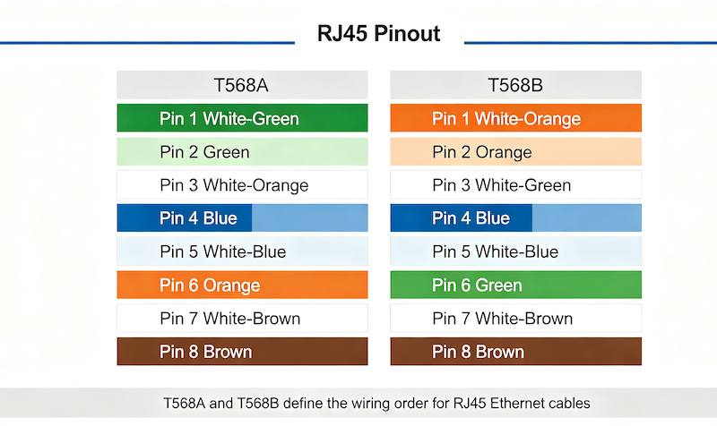
RJ45 Pinout Guide: T568A vs T568B Wiring Standards Explained
Complete guide to RJ45 pinout and wiring. Compare T568A vs T568B standards, color codes, straight-through vs crossover cables, and PCB design considerations...

RJ45 vs RJ11: Key Differences, Pinouts, and How to Choose the Right Connector
You are specifying connectors for a new product. The datasheet calls for a modular jack. You look at the footprint—eight contacts. Your...

RJ45 Connector Types: Shielded vs Unshielded — A Field Engineer’s Guide to Smarter Procurement
The Quiet Failure That Costs Thousands A procurement manager in Stuttgart once sent me a batch of unshielded RJ45 connectors for a...