
The Quiet Failure That Costs Thousands
A procurement manager in Stuttgart once sent me a batch of unshielded RJ45 connectors for a new automotive assembly line. The installation looked clean. The cable tests passed. Three weeks later, the network began dropping packets every time the welding robots cycled. The root cause was not a bad switch or a faulty cable run. It was the connectors themselves — plastic-bodied, ungrounded, sitting inches from 480V motor drives.
That story repeats itself in factories, data centers, and broadcast facilities more often than most engineers admit. The RJ45 connector is the most overlooked component in an Ethernet link. Buyers fixate on cable category and switch throughput, then treat the connector as an afterthought. It is not. The choice between shielded and unshielded RJ45 connectors determines whether your network survives its electrical environment or quietly degrades under interference.
This guide is written for the engineer who needs to spec connectors with confidence, and for the procurement professional who needs to justify a parts list to a cost-conscious CFO. No marketing fluff. Just the technical reality of how these components behave in the field.
What an RJ45 Connector Actually Does
An RJ45 connector is an 8-position, 8-contact (8P8C) modular interface. It terminates twisted-pair Ethernet cable and creates the electrical bridge between the cable’s conductors and the device’s internal circuitry. Whether it is a field-crimped plug on a patch cord or a PCB-mounted jack on a switch board, its job is to maintain signal integrity across that boundary.
The connector does not amplify the signal. It does not correct errors. It simply needs to present the lowest possible impedance mismatch, preserve the twist geometry of the pairs as close to the contact point as possible, and — in shielded designs — maintain a continuous Faraday cage from cable shield to equipment ground. When any of these three jobs fails, the entire channel degrades.
Shielded vs. Unshielded: The Fundamental Divide

Unshielded RJ45 Connectors
An unshielded RJ45 connector is housed entirely in plastic — typically polycarbonate or high-temperature nylon. The gold-plated contacts are exposed to the environment with no metallic enclosure. The connector relies entirely on the cable’s internal twist to reject electromagnetic interference (EMI).
When they work: Clean electrical environments. Standard office LANs. Home networks. Retail POS systems. Anywhere the cable run does not parallel power cables, motor leads, or RF transmitters.
The hidden limitation: Unshielded connectors offer zero radiated emission containment. In environments with strict EMC compliance requirements — medical imaging suites, military comms racks, or CE-marked industrial equipment — an unshielded connector can become an antenna. It radiates noise outward just as easily as it admits noise inward.
Shielded RJ45 Connectors
A shielded RJ45 connector wraps the plastic housing in a metal shell — typically nickel-plated brass or zinc alloy. This shell is electrically bonded to the cable’s drain wire and, in PCB-mounted designs, to the board’s ground plane through shield tabs or spring fingers.
The metal shell serves two functions simultaneously:
- Ingress protection: It blocks external EMI from coupling into the differential pairs.
- Egress suppression: It prevents high-frequency signals from leaking out of the connector and violating EMC limits.
Shielded connectors are mandatory for any installation using shielded cable (STP, FTP, S/FTP). Using a shielded cable with an unshielded connector breaks the shield continuity at the termination point, rendering the entire shielding investment useless. Conversely, a shielded connector on unshielded cable provides no benefit and can actually create ground loop issues if the shell finds an unintended path to earth.
The Shielding Hierarchy: Not All “Shielded” Is Equal
Engineers often say “shielded” as if it is a binary state. It is not. The shielding architecture of both the cable and the connector matters deeply.
| Cable/Connector Shielding Type | Construction | EMI Protection Level | Typical Use Case |
|---|---|---|---|
| U/UTP | No shield on cable, no shield on connector | Low | Home networks, small offices |
| F/UTP | Overall foil shield on cable, shielded connector | Moderate | General commercial, bundled cable trays |
| U/FTP | Individual pair foil shields, shielded connector | High | Data centers, high-density patching |
| S/FTP | Individual pair foils + overall braid, shielded connector | Very High | Industrial automation, medical, military |
If you are running Power over Ethernet (PoE) at 90W (PoE++), the shielded path becomes even more critical. The shield acts as a parallel current return path, reducing common-mode noise and thermal rise at the contacts. TIA now recommends Cat6A shielded terminations for continuous high-power PoE delivery. The alternative is contact oxidation, resistance creep, and eventual thermal failure at the jack.
Critical Parameters That Determine Performance
Contact Plating Thickness
The gold plating on RJ45 contacts is not decorative. It prevents oxidation and maintains low contact resistance over thousands of insertion cycles. For standard office use, 3–6 microinches of gold over 50 microinches of nickel is sufficient. For industrial or outdoor applications, 15–30 microinches of gold is the minimum to survive temperature cycling and corrosive atmospheres. Anything less, and you will see intermittent links within two years.
Wire Gauge Compatibility
RJ45 connectors are not universal. A connector rated for 24 AWG stranded patch cable will fail catastrophically if crimped onto 23 AWG solid horizontal cable. The IDC or crimp contacts are sized for a specific conductor diameter. Using the wrong gauge creates cold joints, high insertion loss, and — in the worst case — contact deformation that damages the jack it mates with.
Always verify the connector’s AWG range before ordering. For Cat6A and Cat7 cables, which often use 23 AWG conductors with thicker insulation, you need connectors with larger cable entry barrels and internal load bars to maintain pair separation.
Category Rating vs. Real-World Bandwidth
A Cat6 connector does not automatically guarantee 250 MHz performance. The category rating applies to the entire channel — cable, connectors, and patch cords — tested together. A Cat6 cable with Cat5e connectors will bottleneck at the connector’s limitations. For 10GBASE-T (Cat6A, 500 MHz), you need Cat6A-rated connectors with internal pair separators and tighter impedance control.
Practical rule: Match or exceed the cable category with your connectors. Never downgrade.
The Five Procurement Traps Engineers Fall Into
Trap 1: Buying Shielded Connectors “Just in Case”
Shielded connectors cost 2–3× more than unshielded. They are heavier, bulkier, and require proper grounding to function. If your installation uses UTP cable in a low-EMI office, shielded connectors add cost and complexity with zero performance benefit. Worse, an improperly grounded shielded connector can become a noise sink, attracting interference rather than rejecting it.
Trap 2: Ignoring the Drain Wire
A shielded RJ45 plug has a metal ground tab that must crimp onto the cable’s drain wire. Many installers skip this step or crimp it poorly. Without that bond, the shield is electrically floating — useless. In PCB-mounted shielded jacks, the shield tabs must solder to a solid ground plane with low-impedance vias. A shielded jack on a PCB with no ground stitching is a liability.
Trap 3: Mixing Shielded and Unshielded Components
Shielding is a system, not a component. If your cable is shielded, your connectors must be shielded. Your patch panels must be shielded. Your equipment chassis must provide a ground reference. One unshielded component in the chain breaks the Faraday cage. I have seen contractors install shielded cable with unshielded keystone jacks because “the jacks were in stock.” The resulting alien crosstalk failures took three days to diagnose.
Trap 4: Underspecifying for PoE
Standard RJ45 connectors are rated for 1.5A per pin. PoE++ (802.3bt, Type 4) pushes 90W at 52V, which is 1.73A per pair — above the baseline rating. The contact resistance at each pin junction generates heat. In a dense patch panel with 48 ports, that heat accumulates. Shielded connectors with larger contact surfaces and better thermal dissipation are not optional for high-density PoE deployments. They are survival equipment.
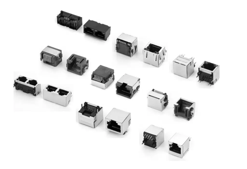
Trap 5: Confusing Connector Types
A field-crimp RJ45 plug is not a keystone jack. A PCB-mount jack is not a panel-mount coupler. Each serves a different mechanical and electrical role:
- RJ45 Plug (Field Crimp): For patch cords. Crimped onto stranded cable. ~750–1,500 mating cycles.
- Keystone Jack: For permanent horizontal cabling. IDC punch-down termination. 5,000+ cycles. Superior NEXT/FEXT performance.
- PCB-Mount Jack: Integrated into device design. May include magnetics (MagJack) for isolation and EMI filtering.
- Panel-Mount Coupler: Pass-through connector for enclosure bulkheads. No termination — just extension.
Buying the wrong type for your application guarantees either installation failure or long-term reliability issues.
When to Choose Shielded: The Decision Matrix
Use this framework when spec’ing your next project:
| Environmental Factor | Unshielded | Shielded |
|---|---|---|
| Cable runs parallel to power lines (>300mm) | No | Yes |
| Proximity to VFDs, welders, or RF transmitters | No | Yes |
| Outdoor or harsh industrial environment | No | Yes |
| Medical devices (EMC compliance required) | No | Yes |
| PoE++ (90W) deployment | Risky | Yes |
| Standard office, home, or retail LAN | Yes | No |
| Cost-sensitive consumer electronics | Yes | No |
The threshold is not subjective. If your environment contains equipment that generates electromagnetic fields above 3 V/m (typical for industrial motor drives), shielded connectors are not a luxury. They are a requirement for maintaining BER (bit error rate) within IEEE 802.3 limits.
Shielded RJ45 Jack: The PCB Designer’s Perspective
For hardware engineers designing boards, the shielded RJ45 jack is a critical EMC component, not just a mechanical interface. A properly specified shielded jack with integrated magnetics (MagJack) combines the connector, isolation transformer, common-mode choke, and Bob Smith termination into a single part. This integration:
- Reduces component count by 6–10 discrete parts.
- Shrinks PCB footprint by 30–50%.
- Improves signal integrity by minimizing the stub length between magnetics and contacts.
When selecting a shielded RJ45 jack for PCB mounting, verify:
- Shield tab configuration: Does it require through-hole soldering, or does it use SMT shield tabs? The grounding method affects your PCB stackup.
- LED integration: Many jacks include link/activity LEDs. Confirm the LED polarity and forward voltage match your design.
- PoE compatibility: For PoE applications, the jack must handle the DC bias current without saturating the integrated magnetics. Check the datasheet for DC resistance and current rating.
- Tab orientation: Tab-up vs. tab-down determines cable egress direction and affects enclosure mechanical design.
Installation Realities: What the Datasheet Won’t Tell You
Crimping Shielded Plugs
The metal shell on a shielded plug adds a grounding step that unshielded plugs do not have. After stripping the cable jacket, you must peel back the foil/braid shield, expose the drain wire, and fold it over the cable jacket so it contacts the plug’s ground crimp tab. Crimp the ground tab first, then the contacts. If the drain wire is too short or improperly positioned, the shield is open.
Pro tip: Use a magnifier to inspect the drain wire position before crimping. A single missed ground connection in a 100-port installation can create an intermittent fault that takes hours to isolate.
Punching Down Shielded Keystone Jacks
Shielded keystone jacks require the cable shield to make contact with the jack’s metal shell. Most designs use a clamp or pressure plate that bites into the foil/braid when the jack cover is closed. If the shield is not fully exposed or the clamp is loose, the shield continuity tester will fail. Always verify with a shield continuity tester, not just a wire map tester.
Grounding at the Patch Panel
Shielded patch panels must be bonded to a common ground bus. The panel chassis connects to the rack ground, which connects to the building’s earth electrode. A floating shield is worse than no shield — it acts as a capacitor, storing charge and discharging it into the data pairs at unpredictable intervals. If your facility lacks a proper ground infrastructure, do not install shielded cabling.
Cost Analysis: The Real Numbers
Let us put aside the sticker price and look at total cost of ownership.
| Component | Unshielded (per unit) | Shielded (per unit) | Delta |
|---|---|---|---|
| Cat6A RJ45 Plug | $0.35 | $0.85 | +143% |
| Cat6A Keystone Jack | $1.20 | $2.80 | +133% |
| Installation Labor (typical) | Baseline | +15–20% | — |
| Shield Continuity Testing | Not required | Required | +$0.10/port |
In a 500-port installation, shielded connectors add roughly $1,200 in material cost and 20% more labor. However, the cost of one EMI-related network outage — lost production, diagnostic time, and emergency contractor rates — typically exceeds $5,000. Shielded connectors pay for themselves if they prevent a single failure.
Sourcing Strategy for Bulk Buyers
If you are procuring RJ45 connectors at volume, structure your BOM around these principles:
- Qualify two suppliers per category. Shielded connector manufacturing requires precision metal stamping and plating control. A single-source supplier with a plating deviation can contaminate an entire production run.
- Request insertion loss and return loss sweep data. Do not accept “meets Cat6A” as a specification. Ask for the actual test plot from 1 MHz to 500 MHz. A quality supplier will provide this.
- Verify shield continuity on every lot. Use a simple ohmmeter test between the connector shell and the cable drain wire. Reject any lot with >0.1Ω resistance.
- Match your connector to your cable’s conductor type. Solid-core horizontal cable needs connectors rated for solid wire. Stranded patch cable needs connectors rated for stranded. “Universal” connectors exist, but they are a compromise on both.
- Plan for lead times. Shielded connectors with integrated magnetics (MagJacks) often carry 12–16 week lead times due to ferrite core availability. Do not let connector availability bottleneck your PCB build.
Final Word: The Connector Is the Channel
The RJ45 connector is the most underestimated component in Ethernet infrastructure. It is also the most common point of failure. A cable can be flawless. The switch can be enterprise-grade. But if the connector introduces impedance mismatch, breaks shield continuity, or oxidizes under thermal load, the entire link degrades.
Shielded connectors are not automatically better. They are better when the environment demands them. Unshielded connectors are not cheap shortcuts. They are the correct choice for clean, cost-sensitive installations. The discipline is in matching the connector to the cable, the cable to the environment, and the environment to the application requirements.
At ElectroSource Global, we do not sell connectors as commodity parts. We spec them as system components — tested for plating consistency, shield continuity, and insertion loss margin. Whether you are building a data center, an industrial control network, or a medical device interface, the right RJ45 connector is the one that disappears into the background and simply works for ten years. That is the standard we build to.
Related Technical Resources:


