
You have just received the first prototype boards from your assembly house. The HDMI port is populated, the traces are routed, and the initial power-on test passes. Then you connect a display—and nothing. No video, no handshake, no EDID read. The scope shows signals at the connector pins, but the display sees nothing.
After two days of debugging, you find it: the HDMI receptacle footprint was mirrored. Pin 1 and Pin 19 were swapped. The connector is physically correct, electrically terminated, and mechanically sound—but the pinout is reversed. The entire board run is scrap.
This scenario is more common than most engineers care to admit. The HDMI 19 pin connector looks straightforward—19 contacts in two staggered rows, a familiar rectangular shape, and a standard footprint that has been used for over two decades. But the devil is in the details: pin numbering conventions, footprint orientation, mounting style selection, and signal integrity requirements all have the potential to derail a design.
Whether you are specifying connectors for a new consumer product, an industrial display, or an automotive infotainment system, understanding the HDMI 19 pin connector is not optional—it is the difference between a product that works and one that generates returns.
This guide covers everything you need to know: the 19-pin pinout, key specifications, PCB mounting options, selection criteria, and common design mistakes to avoid.
Internal link: For a broader comparison of HDMI connector types, see our guide on HDMI Connector Types Explained .
What Is an HDMI 19 Pin Connector?
The HDMI 19 pin connector—formally known as the HDMI Type A connector—is the standard physical interface for High-Definition Multimedia Interface (HDMI) connections. It is the connector found on televisions, monitors, gaming consoles, set-top boxes, projectors, and countless other consumer and industrial electronics.
The “19 pin” designation refers to the number of electrical contacts arranged in two staggered rows within the connector housing. These 19 pins carry digital video, multi-channel digital audio, control signals (CEC, DDC), and a 5V power line—all through a single cable.
Key characteristics of the HDMI 19 pin connector:
- 19 contacts in a two-row staggered configuration
- 0.50 mm pin pitch between adjacent contacts
- Type A form factor—the largest and most common HDMI connector
- Female receptacle for PCB mounting (or male plug for cable termination)
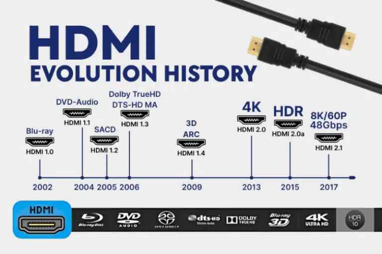
- Supports all HDMI versions from 1.0 through 2.1
- Bandwidth: Up to 48 Gbps with HDMI 2.1
The HDMI Type A connector is often simply called the “HDMI connector” because it is the default format. Type C (Mini HDMI) and Type D (Micro HDMI) are smaller variants for portable devices, but they all share the same 19-pin electrical interface.
External link: For the official HDMI connector naming guidelines, refer to the HDMI Licensing Administrator .
HDMI 19 Pin Connector Pinout
Understanding the pinout is essential for PCB layout, schematic entry, and troubleshooting. The 19 pins are divided into functional groups: TMDS data channels, clock, control lines, power, and grounds.
Pin Numbering Convention
HDMI connectors use two staggered rows of pins. The numbering starts from the right side of the connector when viewed from the mating face. However, pin numbering depends on the view direction—the plug (cable end) and receptacle (PCB connector) views can appear as mirror images.
Critical rule: Always verify the pin numbering against the connector’s datasheet footprint drawing, not against a generic diagram. A footprint that is mirrored will route Pin 1 to the wrong pad, and the board will fail.
Pin Functions by Group
| Pins | Group | Function |
|---|---|---|
| 1-3, 4-6, 7-9 | TMDS Data Channels 0, 1, 2 | Three high-speed differential pairs carrying video, audio, and packet data |
| 10-12 | TMDS Clock | Timing reference for TMDS data |
| 13 | CEC | Consumer Electronics Control—allows device communication |
| 14 | Reserved / HEC | Reserved (HDMI 1.0-1.3) or Ethernet data (HDMI 1.4+) |
| 15 | SCL | I²C serial clock for DDC (Display Data Channel) |
| 16 | SDA | I²C serial data for DDC |
| 17 | DDC/CEC Ground | Ground reference for control lines |
| 18 | +5V Power | 5V power output from source to sink (up to 55mA) |
| 19 | HPD | Hot Plug Detect—signals when a display is connected |
TMDS channels carry the actual audio/video content. Each channel is a differential pair with an associated shield/ground pin for noise reduction.
DDC (Display Data Channel) uses I²C (SCL and SDA) to allow the source device to read the display’s EDID (Extended Display Identification Data)—this is how the source knows what resolutions and formats the display supports.
HPD (Hot Plug Detect) tells the source that a display has been connected or disconnected, triggering the handshake process.
Plug vs Receptacle: Why Orientation Matters
A common source of errors: the plug (male, cable side) and receptacle (female, PCB side) have mirrored pin assignments when viewed from the front. A diagram showing the plug front view will have Pin 1 on the opposite side from a diagram showing the receptacle front view.
Rule: When laying out a PCB footprint, use the receptacle view from the connector datasheet. Do not assume the pinout matches a generic plug diagram.
External link: For detailed pinout diagrams and signal descriptions, refer to the HDMI Specification .
Key Technical Specifications
When evaluating an HDMI 19 pin connector for a design, these specifications determine whether the connector will perform reliably in your application.
Electrical Specifications
| Parameter | Typical Value | Notes |
|---|---|---|
| Contact Resistance | ≤ 10 mΩ (initial) | Higher resistance causes signal degradation and heat |
| Insulation Resistance | ≥ 100 MΩ (unmated) | Prevents leakage between adjacent pins |
| Dielectric Withstanding Voltage | 500 VAC for 1 minute | Ensures insulation integrity under voltage stress |
| Current Rating | 0.5 A per contact | Sufficient for HDMI signal and 5V power requirements |
| Voltage Rating | 40 V DC | Well above the 5V HDMI power rail |
| Impedance | 100 Ω ± 15% (connector area) | Must match PCB differential impedance |
Mechanical Specifications
| Parameter | Typical Value | Notes |
|---|---|---|
| Mating Cycles | 10,000 cycles | Standard for high-quality HDMI connectors |
| Pin Pitch | 0.50 mm | Standard for Type A connectors |
| Operating Temperature | -20°C to +85°C (standard) | Extended ranges available: -40°C to +100°C |
| Housing Material | Glass-filled high-temperature resin | UL94V-0 flammability rating |
| Contact Material | Brass or copper alloy | Gold-plated in contact area |
| Shell Material | Steel or copper alloy | Tin or nickel plated for corrosion resistance |
Contact Plating
Contact plating is critical for signal integrity and durability. The standard for HDMI connectors is:
- Contact area: Gold plating (typically 15µ” to 30µ”) over nickel underplating
- Solder tails: Tin plating for solderability
- Shell: Tin or nickel plating over base metal
Gold plating provides low contact resistance, excellent corrosion resistance, and reliable performance through 10,000 mating cycles. Tin-plated solder tails ensure good wetting during the soldering process.
Mating Cycle Durability
The 10,000 mating cycle rating is an industry standard for HDMI connectors. This rating assumes proper cable insertion and removal. Exceeding the rated cycles can lead to:
- Increased contact resistance from plating wear
- Reduced normal force from contact fatigue
- Intermittent connections or complete failure
For applications with frequent plugging and unplugging (e.g., public kiosks, test equipment), consider connectors rated for higher cycle counts or specify field-replaceable cable assemblies.
Internal link: For more on connector durability and selection, see our Connector Selection Guide .
PCB Mounting Options for HDMI 19 Pin Connectors
HDMI 19 pin connectors are available in several PCB mounting configurations. The choice affects mechanical strength, assembly process, PCB footprint, and cost.
Surface Mount (SMT)
The connector sits on the PCB surface with flat terminals soldered to pads.
Advantages:
- Compatible with high-volume reflow soldering
- Supports double-sided PCB assembly
- Lower profile than through-hole
Trade-offs:
- Lower mechanical strength—solder joints rely on pad adhesion only
- More susceptible to damage from cable strain
- Requires precise stencil design for consistent solder paste deposition
Best for: Consumer electronics, portable devices, and high-volume production where mechanical stress is moderate.
Through-Hole (DIP)
Pins pass through drilled holes in the PCB and are soldered on the reverse side. Many HDMI connectors combine SMT signal pins with through-hole shell retention tabs for mechanical strength.
Advantages:
- Superior mechanical strength—solder wicks through the hole
- Better resistance to cable pull forces
- Easier hand-soldering and rework
Trade-offs:
- Requires drilled holes, consuming board space on all layers
- Not compatible with double-sided component placement (pins protrude)
- Slower assembly (wave soldering or selective soldering)
Best for: Industrial equipment, automotive applications, and any design where mechanical robustness is critical.
Mid-Mount SMT
A recessed variant that lowers the overall profile by partially embedding the connector into the PCB.
Advantages:
- Lowest possible profile above the board
- Ideal for ultra-thin devices
Trade-offs:
- Requires PCB cutout, increasing fabrication cost
- More complex assembly and inspection
Best for: Ultra-thin laptops, tablets, and space-constrained designs.
Orientation: Right Angle vs Vertical
Right Angle (Horizontal)
The connector lies flat with the insertion axis parallel to the PCB.
- Best for edge-mounted designs and devices with side-facing ports
- Most common orientation for consumer electronics
Vertical
The connector stands upright with the insertion axis perpendicular to the PCB.
- Best for top-entry designs where board space is limited but height is available
- Less common than right-angle
How to Choose the Right HDMI 19 Pin Connector
Selecting the right HDMI connector involves balancing mechanical, electrical, and manufacturing constraints.
Step 1: Determine the Application Environment
| Environment | Recommended Features |
|---|---|
| Consumer electronics | SMT, right-angle, standard temperature range (-20°C to +85°C) |
| Industrial equipment | Through-hole or hybrid mounting, extended temperature (-40°C to +100°C), robust shell |
| Automotive | Through-hole with shell retention, extended temperature, vibration-resistant design |
| Portable devices | Mid-mount SMT, low profile, compact footprint |
Step 2: Select the Mounting Style
- High-volume automated assembly? Choose SMT (reflow compatible)
- Mechanical strength is critical? Choose through-hole or hybrid (SMT + through-hole retention tabs)
- Space is extremely constrained? Consider mid-mount SMT
Step 3: Verify Temperature Requirements
Standard HDMI connectors are rated -20°C to +85°C. For automotive or outdoor applications, specify extended temperature ranges:
- -40°C to +85°C
- -40°C to +100°C
Step 4: Check Mating Cycle Requirements
- Standard applications: 10,000 cycles is sufficient
- High-use applications (kiosks, public ports): Consider higher-durability variants
Step 5: Review Compliance Requirements
- RoHS/REACH: Required for most global markets
- UL94V-0: Flammability rating for housing material
- HDMI compliance: Ensure the connector meets the required HDMI version specification
Step 6: Confirm the Footprint
This is where designs fail. Verify the PCB footprint against the connector datasheet. Common issues:
- Mirrored pinout (Pin 1 and Pin 19 swapped)
- Incorrect pad sizes for SMT terminals
- Missing through-hole pads for retention tabs
- Incorrect keep-out areas for the connector body
Internal link: Explore our HDMI Connector portfolio—available in right-angle, vertical, SMT, and through-hole configurations.
Common Design Mistakes and How to Avoid Them
Mistake 1: Mirrored Footprint
The most costly mistake. The HDMI receptacle pinout is easy to mirror because the plug and receptacle views are reversed.
Solution: Always use the footprint from the connector datasheet. Compare the pin 1 location against the mechanical drawing. If possible, have a second engineer review the footprint before finalizing the PCB layout.
Mistake 2: Ignoring Impedance Control
HDMI signals require 100 Ω ± 10-15% differential impedance. Poor impedance matching causes reflections, signal degradation, and failed HDMI compliance testing.
Solution: Route TMDS pairs as controlled impedance differential pairs. Maintain consistent trace spacing and dielectric thickness. Avoid routing traces under the connector body where the impedance will change.
Mistake 3: Inadequate ESD Protection
HDMI ports are exposed to the outside world. Electrostatic discharge (ESD) can damage the HDMI transmitter or receiver ICs.
Solution: Place ESD protection devices (TVS diodes) as close to the connector as possible. Route protected traces with rounded corners, not sharp 90-degree bends. Keep unprotected traces away from protected traces to prevent EMI coupling during an ESD event.
Mistake 4: Overlooking Mechanical Retention
SMT-only connectors rely entirely on solder joints for mechanical strength. Cable strain can pull the connector off the PCB.
Solution: Specify connectors with through-hole retention tabs in addition to SMT signal pins. These tabs provide mechanical anchoring without requiring through-hole signal pins. For high-vibration applications, consider fully through-hole connectors.
Mistake 5: Specifying the Wrong HDMI Version
Not all HDMI 19 pin connectors are qualified for HDMI 2.1. While the physical connector is the same, the signal integrity requirements are more stringent at 48 Gbps.
Solution: If your design requires HDMI 2.1 (4K120Hz, 8K60Hz), specify a connector that is HDMI 2.1 qualified. The connector manufacturer will have test data confirming compliance.
Mistake 6: Forgetting the +5V Power Supply
Pin 18 provides +5V power from the source to the sink (display). Some displays draw significant current from this pin. If the source cannot supply enough current, the display may not be detected.
Solution: Ensure your HDMI transmitter or power supply can deliver at least 55mA on the +5V rail. Check the display’s power requirements if designing for a specific application.
External link: For HDMI compliance testing and specifications, refer to the HDMI Forum .
HDMI 19 Pin Connector vs Mini and Micro HDMI
The HDMI 19 pin connector (Type A) is often confused with its smaller siblings. While all three use 19 pins, they are physically different.
| Feature | Type A (Standard) | Type C (Mini) | Type D (Micro) |
|---|---|---|---|
| Dimensions | 13.9 × 4.45 mm | 10.42 × 2.42 mm | 5.83 × 2.20 mm |
| Pins | 19 | 19 | 19 |
| Primary Use | TVs, monitors, consoles | Cameras, tablets | Action cameras, smartphones |
| Mechanical Durability | Highest | Moderate | Lowest |
| PCB Footprint | Largest | Medium | Smallest |
Critical point: All three connector types carry the same 19 signals. The electrical interface is identical. The difference is purely physical—size, mechanical strength, and PCB footprint.
When space permits, Type A is always preferred for its mechanical robustness and widespread cable availability.
Internal link: For a detailed comparison, see our article on HDMI Type A vs Type C vs Type D .
FAQ
What is an HDMI 19 pin connector?
An HDMI 19 pin connector is the standard Type A HDMI interface with 19 contacts arranged in two staggered rows. It carries digital video, audio, control signals, and 5V power through a single cable. It is the most common HDMI connector, found on televisions, monitors, gaming consoles, and countless other devices.
What is the difference between HDMI Type A and Type C?
Type A is the full-size HDMI connector (13.9 × 4.45 mm) used in most consumer electronics. Type C (Mini HDMI) is a smaller version (10.42 × 2.42 mm) designed for portable devices like cameras and tablets. Both have 19 pins and carry the same signals.
Can this connector support 4K or 8K video?
Yes. The HDMI 19 pin connector itself can support 4K and 8K video when used with the appropriate HDMI version. HDMI 2.1 supports 4K120Hz, 8K60Hz, and dynamic HDR formats. The connector type does not limit the HDMI version capability—it is the same physical interface for HDMI 1.4, 2.0, and 2.1.
What is the typical mating cycle life for this connector?
High-quality HDMI 19 pin connectors are rated for 10,000 mating cycles. This is the industry standard and assumes proper insertion and removal. Exceeding this rating can lead to increased contact resistance and intermittent connections.
What plating options are available for the contacts?
The standard is gold plating (typically 15µ” to 30µ”) over a nickel underplating in the contact area. Solder tails are usually tin-plated for solderability. Gold provides low contact resistance and excellent corrosion resistance through 10,000 mating cycles.
What is the operating temperature range?
Standard HDMI connectors operate from -20°C to +85°C. Extended temperature ranges are available: -40°C to +85°C, and -40°C to +100°C. Automotive and industrial applications should specify extended temperature variants.
Do you offer OEM customization?
Yes. Vistar Electronics supports OEM and ODM customization for HDMI connectors, including plating options, housing color, packaging, and mechanical modifications. Contact our engineering team for specific requirements.
Can I request samples?
Yes. We support fast sampling to help you validate the connector’s fit, form, and function in your design before committing to production quantities.
Final Thoughts
The HDMI 19 pin connector appears simple—19 contacts, a standard footprint, and decades of industry use. But the simplicity is deceptive. Pin numbering conventions, footprint orientation, impedance control, ESD protection, and mechanical retention all have the potential to turn a straightforward design into a costly failure.
Getting the connector right starts with understanding the fundamentals: the pinout, the specifications, the mounting options, and the application requirements. It continues with careful PCB layout—controlled impedance routing, proper ESD protection placement, and verified footprints. And it ends with selecting a connector that is qualified for the required HDMI version and environmental conditions.
At Vistar Electronics, we understand the nuances of HDMI connectors. Our HDMI 19 pin connector portfolio includes Type A receptacles in right-angle and vertical orientations, with SMT, through-hole, and hybrid mounting options. We offer gold-plated contacts, 10,000 mating cycles, extended temperature ranges, and HDMI 2.1-qualified variants. OEM and ODM customization, RoHS compliance, and engineering support are available for global customers.
Whether you are designing a consumer television, an industrial display, or an automotive infotainment system, the HDMI connector choice matters. Choose one that is specified correctly, laid out carefully, and built to last.
For technical specifications, samples, or application support, contact the Vistar Electronics engineering team.


