

Automotive Connector Wafer SMT 8Pin — 2.0mm Right-Angle PCB Header for Automotive Electronics
2.0mm Automotive Connector for Compact PCB and Wire-to-Board Applications
A 2.0mm automotive connector provides a useful balance between circuit density and mechanical handling. Compared with larger-pitch wire-to-board connectors, the 2.0mm format allows more contacts to be placed within a limited PCB area while maintaining a practical layout for harness connections.
This eight-position configuration uses two rows of four contacts. The dual-row arrangement makes it possible to route multiple power, ground, signal, or control circuits through one compact interface. For automotive electronic control units, body electronics, sensor modules, and lighting assemblies, this can simplify PCB-to-harness interconnection without requiring a large connector footprint.
The surface-mount construction is intended for PCB assembly environments where automated placement and reflow soldering are preferred. The right-angle orientation is particularly useful when the mating cable or wire harness needs to approach from the board edge rather than from above the PCB.
For production programs, engineers should confirm the complete mechanical drawing, recommended land pattern, contact rating, mating housing, and applicable derating information before PCB release. The values shown below should be treated as product-selection information and verified against the latest manufacturer datasheet for the specific configuration.
Automotive Wafer Connector — Technical Specifications
| Parameter | Specification | Engineering Notes |
|---|---|---|
| Part Number | 2024WRS-2X04-LPSW1BR | Standard catalog configuration |
| Connector Type | Automotive wafer connector | Wire-to-board PCB interface |
| Pin Count | 8 positions | 2 rows × 4 contacts |
| Pitch | 2.0 mm | Compact connector spacing |
| Mounting | SMT | Surface-mount PCB assembly |
| Orientation | Right angle | Horizontal mating direction |
| Contact Material | Copper alloy | Conductive spring-contact structure |
| Contact Plating | Tin plated / Gold plated | Configuration dependent |
| Housing Material | Glass-filled PA66 or PBT | Verify exact material by drawing or datasheet |
| Housing Color | Black | Standard configuration |
| Operating Temperature | −40°C to +105°C | Confirm final rating for selected configuration |
| Contact Resistance | ≤ 20 mΩ typical | Initial value; verify test conditions |
| Insulation Resistance | ≥ 100 MΩ | Test condition dependent |
| Dielectric Strength | 500V AC / 1 minute | Verify latest product specification |
| Packaging | Bag / Tray | Suitable for prototypes and production |
| Application | Automotive and industrial electronics | ECU, sensors, lighting, control modules and harness interfaces |
SMT Automotive Connector — Key Design Advantages
Compact 2.0mm Pitch
The 2.0mm contact pitch provides eight circuits in a relatively compact footprint. This makes the connector suitable for electronic modules where PCB area is limited but multiple wire-to-board circuits are still required.
Right-Angle PCB Orientation
The horizontal mating direction allows the harness to approach from the board edge. This can simplify enclosure design and reduce the vertical space required above the PCB.
Surface-Mount Assembly
SMT mounting supports automated PCB assembly and reflow processes. Engineers should use the manufacturer’s recommended land pattern and assembly profile when qualifying the component for production.
Polarized and Secure Mating
Polarization features help guide the mating interface and reduce the risk of incorrect orientation during assembly. Compatible locking features can also improve connector retention in vibration-prone equipment.
Tin or Gold Contact Options
Tin plating can provide a cost-effective option for standard applications, while gold plating may be selected for applications where corrosion resistance and stable low-level signal contact are important.
Automotive-Oriented Material Selection
High-temperature engineering thermoplastics can provide dimensional stability in the temperature range required by many vehicle electronic modules. The final material and temperature rating should be confirmed from the applicable specification.
Right Angle Automotive Connector — Recommended Applications
Compact PCB-to-harness connections for engine, transmission, body and other electronic control modules.
Suitable for sensor interface boards and electronic modules where multiple signal circuits must be routed through a compact connector.
PCB connections for LED driver boards, lighting control modules and other compact vehicle lighting electronics.
Door modules, seat controls, mirror electronics, HVAC controls and other cabin electronic assemblies.
PLC I/O boards, machine-control modules, sensor interfaces and industrial automation equipment requiring compact wire-to-board connections.
Electronic control systems for agricultural machinery, construction equipment, trucks and other demanding mobile platforms.
Application selection should be based on actual current, voltage, temperature, vibration, mating-cycle, sealing and environmental requirements. For applications exposed to water, mud, oil or direct underbody contamination, engineers should use a connector specifically qualified for the required ingress-protection level rather than assuming that a standard PCB wafer connector is waterproof.
How to Select an 8-Circuit PCB Connector for Automotive Designs
Selecting a connector for an automotive PCB is not simply a matter of matching the number of pins. Mechanical envelope, mating direction, contact system, PCB footprint, wire size, current load and environmental exposure all affect the final choice.
1. Confirm the Circuit Count
An eight-position interface is useful when several signal or power circuits need to be grouped into one connector. The 2×4 arrangement can provide a balanced PCB layout while keeping the connector footprint relatively compact.
2. Check the Pitch and PCB Footprint
A 2.0mm pitch provides higher contact density than many larger-pitch wire-to-board systems. However, pitch alone does not define PCB compatibility. Pad dimensions, mounting tabs, housing dimensions, polarization features and mechanical keep-out areas must also match the approved drawing.
3. Evaluate the Mating Direction
A right-angle configuration is useful when the cable exits horizontally from the PCB. This is often advantageous in low-height electronic modules, where a vertical connector could increase the enclosure height or interfere with nearby components.
4. Match the Contact Plating to the Environment
Tin and gold plating should not be treated as interchangeable options in every application. Contact material and plating should be selected according to mating frequency, signal level, environmental exposure, corrosion requirements and the applicable electrical specification.
5. Verify the Complete Mating System
A PCB header is only one half of a wire-to-board connection. Before production approval, verify the compatible housing, terminals, wire size, locking mechanism, polarization and mating dimensions. If an alternative to an existing connector is being considered, dimensional and mating compatibility should be confirmed using engineering drawings rather than relying only on a product description.
PCB Layout, SMT Reflow and Assembly Considerations
Correct PCB layout and assembly process control are essential for connector reliability. The recommended footprint should be taken from the latest manufacturer drawing rather than recreated from a product photograph or nominal pitch dimension.
PCB Footprint
Verify the pad size, center-to-center spacing, mounting features and connector keep-out area before releasing the PCB. Leave sufficient clearance around the mating face so the harness connector can be inserted and locked without interference from nearby components or enclosure walls.
Component Placement
Keep tall components away from the connector mating path. Right-angle connectors often sit close to the PCB edge, so the mechanical cutout and cable approach direction should be considered together with the electrical layout.
Reflow Process
SMT assembly should follow the component manufacturer’s approved process window. Peak temperature, time above liquidus, ramp rate, preheat and cooling conditions should be established from the actual housing material and solder process rather than copied from a generic profile.
IPC provides industry guidance covering solder assembly and process exposure for electronic components. For production qualification, consult the applicable IPC standards and technical resources and use the manufacturer’s process recommendations.
Inspection and Quality Control
AOI can be used to check component placement, orientation and visible solder joints after reflow. For high-reliability programs, additional dimensional, electrical and mechanical testing may be required according to the customer’s qualification plan.
Compatibility and Replacement Considerations
This product is listed as an alternative to the JST CPT/eCPT family. However, connector replacement should always be treated as an engineering qualification activity. Even when two connectors have the same nominal pitch and circuit count, differences in housing dimensions, terminal geometry, mating interface, PCB footprint, locking structure or electrical ratings can affect compatibility.
JST’s official CPT documentation describes its automotive wire-to-board family as a 2.0mm-pitch SMT connector with multiple circuit configurations, including 8 circuits. The manufacturer’s published specifications should therefore be used as the reference when evaluating any replacement or second-source option.
See the official JST CPT connector information for the original manufacturer’s series specifications. Before approving a second source, compare the complete mechanical drawing, terminal arrangement, mating housing and electrical specifications.
Quality, Materials and Compliance for Global Sourcing
For overseas procurement teams, connector selection also involves material documentation and regulatory requirements. Vistar Electronics supports OEM and ODM sourcing for connector products and can provide product-specific technical information for engineering evaluation.
RoHS requirements restrict certain hazardous substances in electrical and electronic equipment in the European Union. For applicable projects, customers should request the relevant material declarations and compliance documentation for the specific part configuration.
The official EU RoHS Directive 2011/65/EU provides the regulatory framework for restricted substances in electrical and electronic equipment. Where REACH-related documentation is required, procurement teams should also confirm the latest supplier declarations and substance information for the selected materials.
For automotive programs, buyers may also require traceability, dimensional inspection reports, material declarations, reliability testing, PPAP documentation or customer-specific qualification records. These requirements should be agreed before mass production rather than after the product has entered the assembly line.
OEM, ODM and Bulk Supply Options
Vistar Electronics supplies connectors for OEM, ODM and contract-manufacturing projects. For volume programs, customers can discuss contact plating, housing color, packaging, labeling, compatible mating components and other configuration requirements with the engineering and sales teams.
Prototype and production sourcing should follow the same qualification logic: confirm the drawing, sample, electrical specification, mating system and assembly process before approving the production version. This approach helps reduce the risk of replacing a connector based only on nominal pin count or pitch.
For engineering samples, bulk quotations or customized connector requirements, contact the Vistar Electronics sales team with the required pin count, pitch, mounting direction, PCB application, target quantity and mating connector information.
Related Automotive Connector Resources
For a broader overview of vehicle connector technologies, see the
automotive connector product range
covering different circuit counts, mounting styles and application requirements.
If you are comparing circuit counts, you can also review the
2 Pin SMT wafer automotive connector
and compare its compact configuration with the eight-position version.
For engineers evaluating automotive connector structures and selection criteria, the
Automotive Connectors technical guide
provides additional background on automotive electrical interconnection systems.
8 Pin Automotive Connector FAQ
What is an 8 pin automotive connector used for?
An 8 pin automotive connector can group eight electrical circuits into one compact PCB-to-wire interface. Typical applications include ECU modules, body electronics, sensor boards, lighting control modules, HVAC electronics and industrial control equipment. The exact application depends on the electrical rating, mating system and environmental requirements.
What is the advantage of a 2.0mm pitch connector?
A 2.0mm pitch allows more contacts to be placed in a smaller area than many larger-pitch connector systems. It is useful when PCB space is limited but multiple signal or power circuits still need to be routed through a single wire-to-board interface.
Why choose a right-angle SMT connector?
A right-angle SMT connector directs the mating cable parallel to the PCB surface. This can reduce vertical packaging requirements and make it easier to route a harness toward the edge of an electronic module.
Is this connector a direct replacement for a JST CPT or eCPT connector?
The product is offered as an alternative to the JST CPT/eCPT family. However, direct interchangeability should not be assumed from the pin count or 2.0mm pitch alone. Engineers should compare the complete mechanical drawing, mating interface, PCB footprint, terminal arrangement and electrical specifications before production approval.
Can the contact plating be customized?
Tin-plated and gold-plated contact options are available for different application requirements. For OEM and volume projects, contact Vistar Electronics to confirm available plating, material, packaging and customization options for the required configuration.
Can I request samples before bulk production?
Yes. Samples can be requested for engineering evaluation and product development. When requesting samples, provide the application, expected quantity, mating connector and PCB assembly requirements so the appropriate configuration can be confirmed.
What information should I provide when requesting a quotation?
For an accurate quotation, provide the required pin count, pitch, mounting direction, contact plating, estimated annual quantity, packaging requirements and target application. If you already have a mating connector or PCB drawing, providing that information can also accelerate technical evaluation.
Need an 8-Circuit Automotive PCB Connector?
If your project requires a compact 2.0mm-pitch SMT wire-to-board interface, this eight-position right-angle configuration is a practical option to evaluate. Vistar Electronics can support sample requests, bulk quotations, OEM/ODM requirements and connector configuration discussions.
Send your PCB drawing, mating connector information, required quantity or target application to the Vistar Electronics team for technical review and quotation.
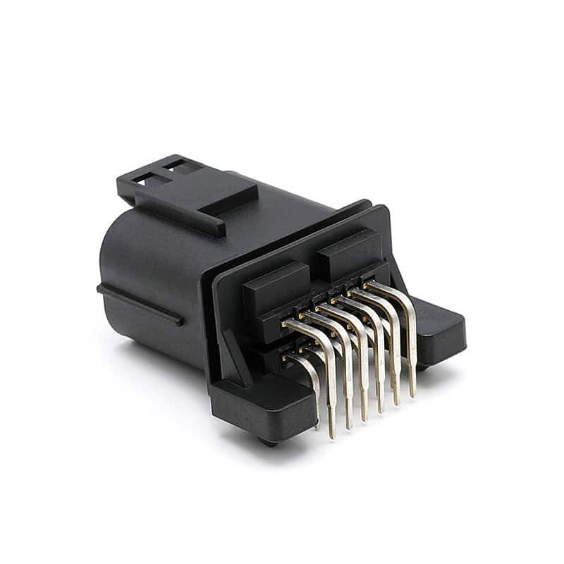
Automotive Header Connector 12P for Vehicle Electronics and Automotive Wiring Systems

16 pole M connector automotive socket

SMT Wafer automotive connector 2pin

2.0MM pitch wafer auto connector
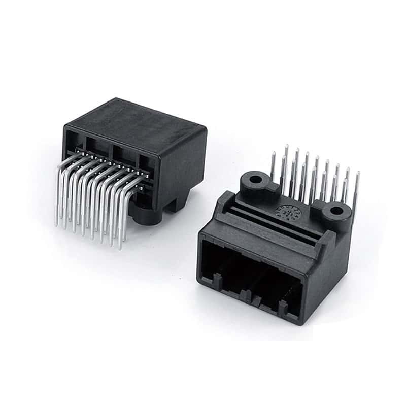
16 Way MX34 Connector for Automotive Electronics and Vehicle Wiring Harness Systems

CPT Connector 4 Way — Compact 2.0mm Automotive Wire-to-Board Housing

Automotive Wire Plug Connector & Harness Connector Solutions
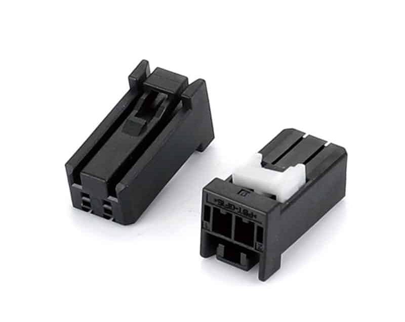
2.00mm Male Housing 2Pin Automotive Crimp Connector

EV Battery Connectors Explained: Types, Functions and Selection Guide
You are designing the high-voltage distribution system for a new electric vehicle platform. The battery pack is specified, the inverter is selected,...
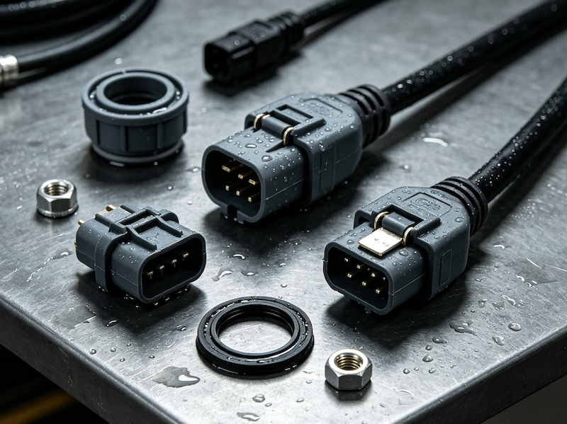
Waterproof Automotive Connectors: A Procurement Engineer’s Guide to Sealing, Standards and Selection
Master waterproof automotive connector selection with this engineer’s guide. Learn IP67 vs IP69K sealing, USCAR testing, material selection, and how to source...

Automotive Connector Types Explained: How to Choose the Right Connector for Every Vehicle System
Automotive Connector Types Explained: How to Choose the Right Connector for Every Vehicle System The Friday Afternoon Call Nobody Wants It is...