

6 Position Vertical Slide Switch 1P6T — SS-16D03 7 Pin DIP PCB Mount for Audio, Industrial & Multi-Mode Consumer Electronics
The SS-16D03 is a 6 position vertical slide switch 1p6t — a compact 7-pin DIP through-hole slide switch with integrated metal mounting brackets, featuring a single-pole, six-throw (1P6T) circuit configuration. Rated 0.5A at DC 50V with a robust 10,000 cycle mechanical life. This 1P6T single pole 6 throw switch PCB measures just 26.4 mm × 8.2 mm, making it ideal for multi-position selector applications in audio equipment, test instruments, industrial control panels, and consumer electronics where space-efficient rotary or DIP switch alternatives are impractical. Bag/Tray packaging. Free sample available for qualified projects.
6 Position Vertical Slide Switch 1P6T — SS-16D03 Product Overview
The SS-16D03 is a 6 position vertical slide switch 1p6t engineered for applications requiring multiple discrete circuit states in a compact, user-accessible format. Unlike rotary switches that require circular panel cutouts and occupy significant PCB area, or DIP switches that demand tool-based actuation and offer limited position counts, this vertical slide switch provides six distinct positions in a linear, finger-operated package that slides smoothly along its major axis.
The 1P6T single pole 6 throw switch PCB configuration connects a single common input to any of six independent output circuits, enabling functions such as input source selection, gain staging, filter bandwidth setting, voltage range switching, and mode configuration — all controlled by a single intuitive slider. The vertical orientation positions the actuator perpendicular to the PCB surface, allowing the switch to protrude through a narrow slot in the top or front panel of an enclosure, minimizing panel cutout complexity compared to rotary alternatives.
With a compact 26.4×8.2mm compact slide switch DIP footprint, this switch occupies minimal PCB real estate while delivering robust mechanical performance. The integrated metal mounting brackets provide snap-in retention to the PCB before soldering, ensuring precise positioning during wave or hand soldering operations and preventing switch displacement during assembly, handling, and end-user operation. The 10,000 cycle operating life exceeds typical consumer-grade slide switches, making this component suitable for products subjected to frequent mode changes, calibration adjustments, or field configuration updates.
SS-16D03 7 Pin DIP Slide Switch — Full Technical Specifications
| Parameter | Value | Notes |
|---|---|---|
| Part Number | SS-16D03 | Standard catalog item |
| Switch Type | 6 Position Vertical Slide Switch 1P6T | Single pole, six throw |
| Circuit Function | 1P6T (SP6T) | 1 common, 6 selectable outputs |
| Pin Count | 7 Pins | 1 COM + 6 throw positions |
| Mounting Type | DIP Through-Hole with Bracket | Vertical PCB mount, metal snap-in brackets |
| Actuator Orientation | Vertical (Perpendicular to PCB) | Top-panel or front-panel access |
| Body Dimensions | 26.4 mm × 8.2 mm | Compact linear footprint |
| Voltage Rating | DC 50V | Maximum working voltage |
| Current Rating | 0.5A | Maximum switching current |
| Contact Resistance | ≤ 50 mΩ | Initial value at rated load |
| Insulation Resistance | ≥ 100 MΩ | At 500V DC |
| Dielectric Strength | 500V AC / 1 minute | No breakdown or flashover |
| Operating Force | 150 – 350 gf | Smooth sliding action with detent feedback |
| Operating Life | 10,000 cycles | Mechanical endurance rating |
| Contact Material | Silver-plated or Gold-plated Copper Alloy | Low resistance, oxidation resistant |
| Actuator Material | High-Grade Thermoplastic | Ribbed for grip; black standard |
| Bracket / Housing | Stamped Metal with Insulator Base | Provides snap-in PCB retention |
| Operating Temperature | −25°C to +85°C | Commercial and light-industrial grade |
| Storage Temperature | −40°C to +85°C | Long-term storage conditions |
| Soldering Method | Wave or Hand Soldering | Compatible with lead-free solder |
| Packaging | Bag / Tray | Production and prototype friendly |
Why Engineers Choose the SS-16D03 1P6T Single Pole 6 Throw Switch PCB for Multi-Position Circuit Control
1P6T Configuration — Six Discrete States in One Compact Switch
The single-pole, six-throw design provides six mutually exclusive output paths from one common input, eliminating the need for multiple SPST switches, complex relay matrices, or microcontroller-controlled multiplexers. This simplifies BOM, reduces PCB area, and provides intuitive, tactile user control without firmware dependencies. Ideal for input selectors, gain stages, filter banks, voltage dividers, and mode configuration where the user must visibly and physically confirm the selected state.
26.4 × 8.2 mm Compact Footprint — Space-Efficient Linear Layout
The 26.4×8.2mm compact slide switch DIP body occupies minimal PCB area while providing six distinct positions along a linear axis. Unlike rotary switches that require circular keep-out zones and occupy significant board space, this rectangular footprint fits neatly into tight layouts between ICs, connectors, and passive components. The narrow 8.2 mm width allows placement in slim enclosures and alongside dense component populations.
Integrated Metal Brackets — Secure Snap-In PCB Retention
The stamped metal mounting brackets snap into PCB slots before soldering, holding the switch precisely in position during wave soldering, handling, and transport. This prevents the displacement, rotation, and floating common with bracket-less alternatives, ensuring consistent actuator alignment with the enclosure panel slot. Post-soldering, the brackets absorb sliding and insertion forces, protecting solder joints from fatigue and extending product lifetime in high-usage applications.
0.5A 50V Rating — Versatile for Signal and Small-Power Switching
The 0.5A at 50V DC rating covers a wide range of applications including audio signal routing, sensor input selection, low-power relay coil driving, LED mode indication, and microcontroller GPIO configuration. The 50V voltage headroom accommodates 5V, 12V, 24V, and 48V systems with adequate safety margin, while the conservative current rating ensures minimal contact heating and extended electrical life under continuous operation.
10,000 Cycles — Durable for Professional and Industrial Use
With a 10000 cycle vertical slide switch 0.5A endurance rating, this switch outperforms economy-grade alternatives rated for only 3,000–5,000 cycles. Suitable for test equipment subjected to daily calibration changes, audio mixers with frequent input selection, industrial controllers requiring regular reconfiguration, and consumer products with mode-dependent feature sets. The detent mechanism provides positive position feedback at each of the six stops, preventing accidental mid-position states and ensuring reliable contact engagement.
Vertical Actuation — Intuitive Top-Panel User Interface
The vertical slider orientation rises perpendicular to the PCB surface, requiring only a narrow rectangular slot in the enclosure top or front panel. This is simpler to machine than the circular cutout required for rotary switches and provides better environmental sealing than the large aperture needed for potentiometers. The ribbed actuator texture ensures positive finger grip even with gloved hands, oily industrial environments, or limited tactile feedback conditions.
Where to Use the 10000 Cycle Vertical Slide Switch 0.5A — Applications for Audio, Test, Industrial & Consumer Electronics
Input source selectors, microphone/line switching, gain staging controls, EQ band selection, and monitor routing on mixing consoles, audio interfaces, guitar amplifiers, and professional sound equipment where tactile position confirmation is essential.
Range selection switches on multimeters, bandwidth filters on oscilloscopes, attenuation settings on signal generators, and function mode selectors on laboratory equipment where frequent calibration and measurement configuration changes demand reliable mechanical switching.
Mode selectors on PLC interface boards, manual/auto switching on motor controllers, configuration setting on sensor interface modules, and parameter selection on process control equipment where robust through-hole mounting and visible switch state are critical for operator safety.
Channel selectors, antenna switching, impedance matching networks, and filter bank configuration on radio transceivers, signal analyzers, and communication test sets where multi-position circuit routing is required in compact front-panel layouts.
Difficulty level selectors, game mode configuration, input source switching on AV receivers, and feature enablement on retro gaming hardware, portable media players, and multi-function remote controls where user-accessible mode selection enhances product versatility.
Logic level configuration on FPGA development boards, address setting on microcontroller evaluation kits, protocol selection on communication training platforms, and experiment mode switching on STEM learning hardware where visible switch states aid student comprehension.
SS-16D03 PCB Layout, Bracket Integration & Assembly Guidelines
Proper PCB design and mechanical integration are essential to achieving the full reliability potential of this 6 position vertical slide switch 1p6t. Follow these engineering best practices:
Footprint & Pad Design
- Use the manufacturer-recommended land pattern. The 7-pin DIP configuration with integrated bracket slots requires precise hole diameter, pad sizing, and slot placement to ensure proper solder joint formation, mechanical stability, and actuator alignment. Verify the footprint against the official datasheet before PCB fabrication.
- Maintain adequate solder mask clearance between adjacent pads to prevent solder bridging during wave soldering. A minimum 0.25 mm solder mask web is recommended for the closely spaced 7-pin arrangement.
- Include position markings on the PCB silkscreen to indicate position 1 through position 6, and mark the common (COM) pin location. This simplifies assembly verification, troubleshooting, and user documentation.
- Bracket slot dimensions: The metal snap-in brackets require precisely sized PCB slots (typically 1.0–1.2 mm wide, 3–4 mm long) for secure retention. Slots that are too narrow prevent proper insertion; slots that are too loose compromise mechanical stability and may allow switch rotation during actuation.
Signal Routing & Circuit Design
- Route common (COM) trace centrally. Position 1 is typically the center pin; route this trace to a central location on the PCB to minimize trace length differences to the six output positions, reducing parasitic capacitance and inductance variations between switch states.
- Keep output traces separated. Maintain adequate spacing between traces routed to positions 1–6 to prevent crosstalk, especially when switching high-frequency signals or multiplexed digital buses. For audio applications, consider ground fill or guard traces between signal paths.
- Implement pull-up or pull-down resistors on unused positions if the downstream circuit requires defined logic states when a particular throw is not selected. The 1P6T switch connects COM to only one position at a time; all other positions float.
- Current derating: While rated for 0.5A, consider derating to 0.3A for continuous operation in elevated ambient temperatures (>60°C) or when switching inductive loads, to maximize contact life and minimize resistive heating.
Mechanical & Enclosure Integration
- Reserve panel slot clearance. The vertical actuator requires a narrow rectangular slot in the enclosure top or front panel, typically 6–8 mm wide and 2–3 mm tall, with adequate length to accommodate the full 6-position slider travel. Verify actuator travel distance and protrusion height against the datasheet before enclosure design finalization.
- Provide mechanical support. For switches subjected to frequent or forceful actuation, ensure the enclosure material surrounding the slot is sufficiently rigid to prevent flexure that could bind the slider. Consider adding a bezel or escutcheon plate for reinforcement in thin-walled plastic enclosures.
- Position indication: Consider adding silkscreen labels, engraved markings, or an adjacent LED indicator array on the panel to show the currently selected position, enhancing user experience and reducing configuration errors in multi-mode equipment.
Soldering Recommendations
- Wave soldering: Preheat to 100–130°C, wave temperature 250–260°C, dwell time 4–6 seconds. The through-hole pins and bracket legs provide excellent solder wetting and joint strength. Ensure adequate flux activation for complete barrel fill on all 7 pins and 2 bracket legs.
- Hand soldering: Use a 300–350°C iron tip, apply heat to the pad and lead simultaneously, and feed solder from the opposite side. Avoid prolonged heating that could deform the plastic actuator or insulator base. Solder bracket legs first to establish mechanical stability before soldering signal pins.
- Post-solder inspection: Verify all 7 pins exhibit complete barrel fill with concave solder fillets. Check bracket leg solder joints for adequate wetting to both PCB pad and component leg. Confirm switch sits flat against the PCB without tilt or rocking.
For the official mechanical drawing, recommended PCB footprint with bracket slots, 3D STEP model, and pinout diagram, please contact our sales team or request the SS-16D03 datasheet.
Quality Assurance & Manufacturing Standards
All Vistar slide switches, including this 6 position vertical slide switch 1p6t, are manufactured under stringent quality management systems with comprehensive testing at every production stage:
- 100% electrical testing: Every switch is tested for contact resistance, insulation resistance, and dielectric withstand voltage before shipment
- Operating force verification: Statistical sampling confirms sliding force and detent engagement remain within the 150–350 gf specification across production lots
- Dimensional inspection: Automated optical measurement confirms body dimensions (26.4 × 8.2 mm), pin spacing, bracket coplanarity, pin-to-bracket alignment, and actuator travel distance
- Position accuracy testing: Representative samples verify that the common pin connects to exactly one throw position at each of the six detent stops, with no bridging or floating states
- Life testing: Representative samples undergo 10,000 cycle endurance testing with automated sliding actuation to validate mechanical durability, contact resistance stability, and detent retention
- Environmental testing: Thermal cycling, humidity exposure, and salt spray testing confirm performance under challenging conditions
- RoHS & REACH compliance: Full material composition documentation available for regulatory compliance and international export
Our manufacturing facilities maintain ISO 9001 quality management certification with full lot traceability. Certificate of Conformance (COC), material safety data sheets, and RoHS test reports are available upon request for customer qualification and audit requirements.
Engineering Resources & Related Slide Switch Products
For comprehensive guidance on slide switch selection, multi-position circuit design, and industrial application best practices, explore these authoritative resources:
- SPDT Slide Switch: A Classic Solution for Precision Control and Circuit Routing — Comprehensive coverage of slide switch circuit configurations, wiring diagrams, and selection criteria for signal path management in audio and industrial applications.
- Mini Slide Switches for High-Precision Medical Devices: 5 Critical Applications & Reliability Verification Methods — Expert analysis of slide switch reliability requirements in precision equipment, including verification methods and compliance considerations applicable to test and measurement instruments.
- Best Mini Slide Switch in Implantable Devices: How are long-term biocompatibility and hermetic sealing ensured through special packaging processes? — Advanced discussion of specialized slide switch packaging and reliability engineering for demanding applications.
Explore our full range of Slide Switches for alternative configurations including SPDT (1P2T), DPDT (2P2T), 2P6T, horizontal mount, SMD, and custom position-count options for your specific application.
6 Position Vertical Slide Switch 1P6T — Frequently Asked Questions
What is the difference between 1P6T and a rotary switch with 6 positions?
A 1P6T slide switch like this model provides six discrete circuit positions along a linear axis, actuated by a finger-operated slider that moves in a straight line. The 6 position vertical slide switch 1p6t configuration requires only a narrow rectangular slot in the enclosure panel and occupies a compact rectangular footprint on the PCB.
A 6-position rotary switch provides the same six circuit states but requires circular panel cutout, occupies a larger circular PCB keep-out zone, and typically demands greater mounting depth behind the panel. Rotary switches often offer higher current ratings and more poles but are bulkier, more expensive, and less intuitive for rapid position changes in confined spaces.
Choose a slide switch when:
- Panel space is limited to a narrow slot rather than a circular aperture
- PCB area is constrained and a rectangular footprint fits better than a circular one
- Rapid, linear position changes are preferred (e.g., input source selection on audio equipment)
- Cost minimization is important — slide switches are typically less expensive than equivalent rotary switches
- Front-panel sealing is required — a narrow slot is easier to gasket than a circular hole
Choose a rotary switch when:
- Higher current or voltage ratings are required (rotary switches often support 1A+ and 250V+)
- Multiple poles (2P6T, 3P6T, 4P6T) must switch simultaneously
- Detent feel and position indication are less critical than electrical robustness
- Panel mounting torque and anti-rotation features are required for heavy industrial use
How does the 7-pin 1P6T circuit function work?
The SS-16D03 7 pin DIP slide switch uses 7 pins to implement a single-pole, six-throw (1P6T) circuit:
- Pin 1 (typically center): Common (COM) — the input signal or power source that is routed to one of six outputs
- Pins 2–7: Throw positions 1 through 6 — the six independent output circuits
When the slider is moved to position 1, the internal contact mechanism connects COM to Throw 1. Moving to position 2 connects COM to Throw 2, and so on through position 6. The switch is break-before-make, meaning the COM connection breaks from the previous throw before connecting to the new throw — preventing momentary shorting between adjacent positions during switching.
At any given slider position, exactly one throw is connected to COM; all other five throws remain electrically open (floating). This is fundamentally different from a binary-coded rotary switch or DIP switch array, where multiple bits change simultaneously to encode a digital value. The 1P6T switch provides analog-style routing with visible, tactile position confirmation.
Typical wiring applications include:
- Audio input selector: COM = preamp input; Throws 1–6 = CD, Tuner, Phono, Aux, Bluetooth, USB sources
- Gain stage selector: COM = amplifier input; Throws 1–6 = different resistor divider ratios (0 dB, +6 dB, +12 dB, +18 dB, +24 dB, +30 dB)
- Voltage range selector: COM = ADC input; Throws 1–6 = different voltage divider ratios for multimeter range switching
- Filter bank: COM = signal path; Throws 1–6 = low-pass, high-pass, band-pass, notch, all-pass, bypass filters
Can this switch be used to select between AC line voltages or high-power DC rails?
No. The SS-16D03 is rated for 0.5A at DC 50V maximum. This rating is suitable for:
- Low-voltage DC signal routing (audio, sensor, logic-level signals)
- Small relay coil switching (verify coil current is under 0.5A)
- LED mode indication and low-power control circuit selection
- Microcontroller GPIO configuration and address setting
It is not suitable for:
- AC mains voltage switching (120V AC, 230V AC, 277V AC) — the insulation and contact gap are inadequate for line voltage safety
- High-current DC power distribution (1A+, 5A+, motor loads) — contact heating and arcing will rapidly degrade the switch
- Inductive load switching without snubber protection — relay coils, solenoids, and motors generate back-EMF that damages small signal contacts
- Capacitive load switching (power supply input selection, large filter capacitor banks) — inrush currents exceed the 0.5A rating
For AC line voltage or high-current switching, use appropriately rated power relays, contactors, or dedicated power rotary switches with UL/CSA/VDE certification. The SS-16D03 is a signal-level switch designed for control and routing applications, not power distribution.
What is the MOQ, lead time, and can I request a free sample?
Standard MOQ is 3,000 to 5,000 pieces depending on packaging specification, with a typical production lead time of 2–4 weeks. Free samples are available for qualified engineering evaluations, prototype builds, and product development projects.
To request samples, contact sales@vistarelectronics.com with your company information, target application (audio mixer, test equipment, industrial controller, etc.), estimated annual usage, and part number (SS-16D03). Alternatively, click the “Get a Quote” button at the top of this page to submit your inquiry directly.
For high-volume OEM customers and contract manufacturers, custom specifications are available including alternative actuator colors (white, red, blue for position identification), modified bracket dimensions for specific PCB thicknesses, special pin plating (gold flash for high-reliability applications), and custom tape & reel packaging for automated assembly lines. Volume pricing and long-term supply agreements are available for programs with forecasted annual requirements above 50,000 pieces.
Is this switch suitable for outdoor or high-vibration environments?
The standard SS-16D03 is rated for −25°C to +85°C with a thermoplastic actuator and metal bracket housing, making it suitable for typical indoor commercial, consumer, and light-industrial environments. The through-hole mounting and metal brackets provide good mechanical stability for moderate vibration conditions.
For high-vibration environments (vehicle underhood, heavy machinery, aerospace), consider the following enhancements:
- Adhesive staking: Apply epoxy or thread-locking compound to the bracket legs after soldering to prevent bracket flexure and solder joint fatigue
- Panel reinforcement: Use a metal escutcheon plate or bezel to prevent enclosure slot elongation and slider binding under vibration
- Conformal coating: Apply protective coating to the PCB assembly to prevent moisture and dust ingress through the switch body
For outdoor or washdown environments with direct exposure to rain, high humidity, or pressure washing, the standard open-frame design is not adequately sealed. Vistar offers enhanced environmental protection options including:
- Sealed slide switch variants with silicone boot actuators and gasket interfaces
- Dust-tight designs with enclosed slider mechanisms
- IP-rated switch families for marine, agricultural, and outdoor applications
Contact our engineering team to discuss your specific environmental and vibration requirements, and we will recommend the appropriate switch series, protection strategy, and mounting enhancements for your application.

8 Pin DIP slide switch 2p3t vertical

vertical slide switch 4 position
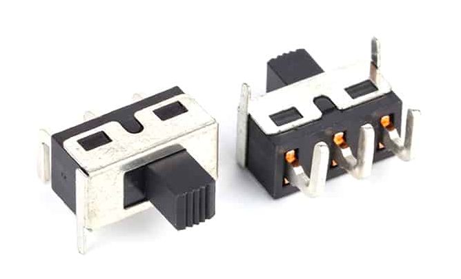
SS-12D11 Miniature Slide Switch SPDT, 3-Pin ON-ON for PCB Mounting

2 Pin Vertical Slide Switch 1P2T — SS-12D16 Right-Angle PCB Mount

Vertical Slide Switch 2P4T for 10-Pin DIP PCB Applications

wire solder slide switch vertical 1p2t

Vertical Slide Switch DIP 8 Pin — SS-23L10 Through-Hole 8-Pin Vertical Slide Switch for Audio, Instrumentation & Industrial Controls

Small Slide Switch DPDT 8-Pin for Compact Vertical PCB Designs

Mini Slide Switches for Medical Devices: Selection Guide, Applications & Reliability
Selecting mini slide switches for medical devices? Get guidance on electrical ratings, sterilization, SMT vs through-hole, and reliability. Ensure patient safety. When...

Mini Slide Switch Reliability: 8 Factors That Affect Long-Term Performance
What really determines mini slide switch reliability? Explore 8 factors from contact material to PCB mounting that impact lifespan. Improve durability in...
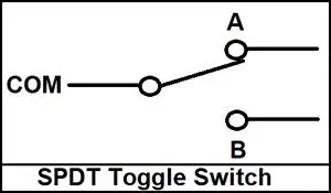
SPDT Slide Switch: A Classic Solution for Precision Control and Circuit Routing
In the control and signal path selection of electronic systems, slide switches have always held an indispensable position due to their intuitive...