
In the control and signal path selection of electronic systems, slide switches have always held an indispensable position due to their intuitive physical operation, reliable state retention, and economical cost.
Among them, the Single Pole Double Throw (SPDT) slide switch, as a basic yet powerful configuration, enables precise selection between two independent circuit paths using a single control point, making it widely used in numerous fields from consumer electronics to industrial equipment.
I. Core Definition and Working Principle
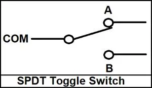
1. Basic Definition: An SPDT slide switch is a manually operated electromechanical component. “Single Pole (SP)” refers to its having a set of independent moving contacts (Common, or COM terminal). “Double Throw (DT)” means that this set of moving contacts can be switched between two fixed, stationary contacts (usually marked NO – Normally Open and NC – Normally Closed, or A/B).
Its mechanical structure allows the user to slide an external handle, driving an internal slider that establishes a physical and electrical connection between the moving contact and one of the stationary contacts, while simultaneously disconnecting it from the other, thus changing the circuit path.
2. Key Operating Mode: An SPDT slide switch is essentially a “break-then-make” switch. During sliding, the moving contact first completely disengages from one stationary contact before connecting to the other. This ensures that no accidental short circuit occurs between the two paths during switching, which is crucial for protecting sensitive circuits or power switching.
II. Internal Structure and Design Variations
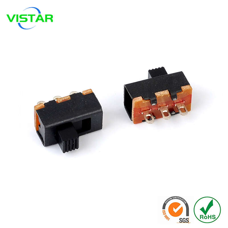
A typical SPDT slide switch consists of the following core components:
- Contact System: Typically made of a copper alloy (such as phosphor bronze) and may be gold- or silver-plated to reduce contact resistance, enhance corrosion resistance, and extend lifespan. This is the core component determining the switch’s electrical performance (current carrying capacity, contact resistance).
- Slider and Drive Mechanism: A slider, made of plastic or metal, translates the linear motion of the external handle into precise displacement of the internal contacts. The mechanism often incorporates springs or ball bearings to provide a clear, tactile feedback (“click”) and accurate positioning, preventing positional drift due to vibration.
- Housing and Terminals: An insulating housing (typically PBT or nylon) provides protection and isolation. Terminal types are diverse, including through-hole or surface-mount (SMT) leads for printed circuit board (PCB) mounting, and quick-connect or screw terminals for panel mounting and wire connections.
Main Design Variations:
- Mounting Methods: Vertical/horizontal PCB mounting, front/rear panel mounting.
- Terminal Types: Through-hole, SMT, wire-type.
- Handle Types: Miniature, standard, long-handle, and sealed types with dust and splash protection.
- Circuit Variations: Based on the SPDT, a three-position switch with a central “off” position ((ON)-OFF-(ON)) can be derived, where the moving contact can move between left, center (floating off), and right positions.
III. Core Performance Parameters and Selection
When selecting an SPDT slider switch, the following key parameters must be considered:
1. Electrical Parameters:
- Rated Current and Voltage: This is the primary consideration. Small signal switches may have a rating of only 0.1A@50V DC, while power switches can handle several amperes to tens of amperes. It is essential to distinguish between AC and DC ratings, as arc extinguishing is more difficult when disconnecting DC inductive loads, and DC ratings are typically much lower than AC ratings.
- Contact Resistance: Measured in milliohms (mΩ), low and stable contact resistance reduces power loss and heat generation.
- Insulation Resistance and Bandwidth Rating: These measure the switch’s ability to prevent leakage and breakdown between different circuits.
2. Mechanical and Life Parameters:
- Operating Force and Feel: The force required for switching and a clear tactile feedback are important for the user experience.
- Mechanical Life: This refers only to the number of physical operations the switch structure can withstand, typically ranging from tens of thousands to hundreds of thousands of times. * Electrical Life: The number of times a switch can reliably complete switching operations under a specified load. Electrical life is much shorter than mechanical life, especially when switching high current or inductive loads.
3. Environmental and Reliability Parameters:
- Protection Rating: IP rating indicates dust and water resistance; for example, IP67 is suitable for harsh environments.
- Operating Temperature Range: Industrial-grade switches typically support a range of -40°C to +85°C or wider.
- Soldering Heat Resistance: For PCB-mounted switches, they must withstand the high temperatures of reflow or wave soldering.
IV. Classic and Innovative Applications
1. Circuit Mode Selection:
- Power Supply Selection: Switches between two power sources (e.g., battery and adapter) to power the device.
- Signal Routing: Selects different input sources in audio devices or different sensor signals in measuring instruments.
- Logic Level Configuration: Sets high and low levels in digital circuits for device address configuration and mode selection (e.g., normal/test mode).
2. Function Control:
- Motor Control: Switches the forward and reverse rotation of a DC motor.
- Lighting Control: Allows selection between two different lighting loads.
- Safety and Bypass: Serves as a manual bypass switch, providing a backup solution in case of automatic control system failure.
V. Selection Guide and Future Trends
Core Selection Considerations:
- Load First: Clearly define whether the switch needs to control a small signal, medium current, or power load. This is the primary basis for selecting the switch’s electrical rating.
- Environmental Matching: Consider the humidity, dust, chemical corrosion, and vibration of the operating environment to select an appropriate sealing rating and materials.
- Installation and Interaction: Select the shape based on PCB layout space or panel opening size, and choose the handle’s force and feel based on user operation frequency and experience.
Development Trends: While the fundamental principles remain unchanged, SPDT slid switches continue to evolve: miniaturization to adapt to high-density electronic products; the use of more environmentally friendly materials and plating to comply with regulations such as RoHS; and higher reliability and consistency to meet the increasingly stringent requirements of automotive electronics and industrial automation.
Conclusion
With its simple and clear operating logic, robust and reliable physical structure, and flexible design forms, the SPDT slide switch perfectly embodies the engineering philosophy of “simplicity is beauty.” It is not only a cornerstone component for realizing circuit function control but also an intuitive and reliable physical medium for human-machine interaction.
In today’s highly integrated and digital world, it continues to play an irreplaceable and crucial role in situations requiring state determination, direct operation, or as a safety backup. Understanding and correctly applying SPDT slide switches is a fundamental skill for every hardware designer and systems engineer. To know more, you can refer to this post: Slide Switches Selection Guide: From Form Factor to Function.


