
Compare right angle vs vertical DisplayPort connectors for PCB mounting. Learn about mechanical fit, PCB layout, applications, and how to choose the right DisplayPort connector for your design.
You are laying out a new industrial display controller. The enclosure has a rear panel cutout for video output, and the PCB sits parallel to the back plane. The engineering team is debating: should the DisplayPort connector be right-angle or vertical? One engineer argues for the space efficiency of vertical mounting; another insists that right-angle is the only way to align with the chassis opening.
This is not a trivial decision. The choice between a right angle and vertical DisplayPort connector determines how the cable exits the enclosure, how much PCB space the connector consumes, how the board fits into the chassis, and how easily the assembly can be manufactured.
For PCB designers, mechanical engineers, and procurement professionals, understanding the difference between these two mounting styles is essential for avoiding costly respins and ensuring reliable field performance.
This guide compares right angle and vertical DisplayPort connectors across mechanical fit, PCB layout, applications, and selection criteria.
Internal link: For an overview of all DisplayPort connector options, see our DisplayPort Connector Product Center .
What Is a DisplayPort PCB Connector?
A DisplayPort PCB connector is a 20-pin receptacle mounted directly onto a printed circuit board, providing the physical interface between the board and a DisplayPort cable. DisplayPort is a digital display interface developed by VESA (Video Electronics Standards Association) in 2006, designed to transmit high-quality video and audio between a source (PC, laptop, GPU) and a display.
The standard full-size DisplayPort receptacle carries the complete 20-pin VESA signal assignment—all four Main Link differential pairs (ML_Lane 0–3), the AUX channel, Hot Plug Detect (HPD), CONFIG1, CONFIG2, and power/ground pins. This full implementation supports DisplayPort 1.2 (up to 4K@60Hz), DisplayPort 1.4 (up to 8K@60Hz with DSC), and is forward-compatible with DisplayPort 2.1 source devices.
DisplayPort PCB connectors are available in multiple mounting orientations to accommodate different enclosure designs and PCB layouts.
Internal link: For the technical background of the DisplayPort interface, see our article DisplayPort Interface: An Efficient Transmission Standard .
What Is a Right Angle DisplayPort Connector?
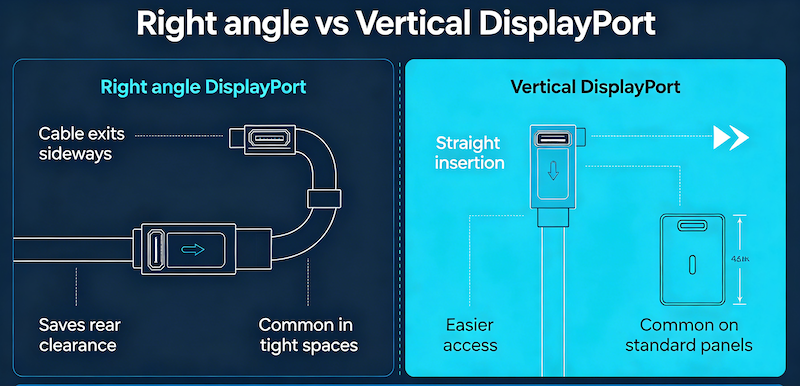
A right angle DisplayPort connector positions the DisplayPort socket opening perpendicular to the PCB surface and parallel to the board edge—the cable exits the connector laterally toward the side of the board.
This is the classic configuration for rear-panel and side-panel DisplayPort ports on desktop monitors, set-top boxes, video processing units, and PCIe add-in cards where the DisplayPort cable runs horizontally away from the PCB assembly through a chassis panel cutout.
Common termination styles:
- Right-angle through-hole (DIP): Pins pass through plated holes in the PCB and are soldered on the back side, providing far greater pull-out resistance and resistance to cable side-loads than SMT mounting. This is critical for a full-size DisplayPort receptacle that receives repeated cable insertions and is subject to lateral cable tension. The DIP approach also enables wave-soldering process integration, simplifying high-volume production assembly.
- Right-angle SMT: Surface-mount versions are also available for applications where through-hole soldering is not preferred.
Key mechanical specifications (DP-F-01 example):
- Mating life: 5,000 cycles
- Insertion force: 35N maximum
- Withdrawal retention: 8N minimum
- Contact plating: Gold-plated phosphor bronze
- Shell: Zinc alloy for EMI shielding
Best for:
- Desktop monitors and displays
- AV equipment and set-top boxes
- Docking stations
- PCIe add-in cards
- Industrial panel PCs
- Embedded display controller PCBs
Internal link: Explore our Right Angle DisplayPort Receptacle 20P SMT + Through Hole and DisplayPort Connector Female DIP 20 Pin .
What Is a Vertical DisplayPort Connector?
A vertical DisplayPort connector is mounted with the port opening oriented vertically upward (top-facing), perpendicular to the PCB. The connector sits upright on the board, and cables connect from above. This configuration is common in all-in-one monitor PCBs, table-top docking stations, signal distribution boards, and display controller assemblies where routing the video cable downward to a side-panel port is not practical.
Vertical DisplayPort connectors typically use a hybrid SMT + through-hole mounting structure. The signal pins are surface-mounted while mechanical retention pins pass through the PCB, providing superior mechanical retention compared to pure SMT designs. This makes them ideal for applications subject to frequent cable insertion and vibration.
Key mechanical specifications (DP-F06-15H example):
- Bandwidth support: HBR3 up to 32.4 Gbps (DisplayPort 1.4)
- Mounting: Vertical SMT with through-hole reinforcement
- Height: 15mm (H=15mm)
- Contact plating: Gold-plated for low contact resistance
- Compliance: ISO 9001:2015, RoHS 3, REACH
Best for:
- Graphics cards
- Industrial displays
- Docking stations
- Embedded systems
- Gaming devices
- Digital signage equipment
Key advantage: The upright design helps optimize PCB space while maintaining strong insertion retention for repeated mating cycles.
Internal link: View our Vertical DisplayPort Connector 20 Pin SMT .
Right Angle vs Vertical DisplayPort Connector: Direct Comparison
| Feature | Right Angle | Vertical |
|---|---|---|
| Cable Direction | Lateral (side-exit) | Upward (top-exit) |
| PCB Mounting | Parallel to board surface | Perpendicular to board surface |
| Termination Options | DIP (through-hole), SMT | Hybrid SMT + through-hole |
| Mechanical Strength | Excellent (DIP anchoring) | Good (hybrid design) |
| PCB Space | Requires board-edge clearance | Requires height clearance |
| Chassis Fit | Rear-panel, side-panel cutouts | Top-entry, vertical cable routing |
| Typical Applications | Monitors, AV equipment, PCIe cards | Graphics cards, docking stations, industrial displays |
| Common Part Examples | DP-F-01, DP-F02B | DP-F06-15H |
PCB Layout Considerations
Right Angle Connector Layout
When designing a PCB with a right-angle DisplayPort connector:
- Board-edge placement: The connector must be positioned at the board edge to allow the cable to exit through the chassis panel.
- Keep-out area: Allow clearance for the connector body extending beyond the board edge and for the cable assembly.
- Through-hole routing: DIP versions require plated through-holes for the signal and retention pins, consuming space on all PCB layers.
- Mechanical anchoring: The through-hole DIP anchoring resists lateral cable strain forces characteristic of side-panel connectors.
Vertical Connector Layout
For vertical DisplayPort connectors:
- Height clearance: The connector stands upright, requiring clearance above the PCB (typically 15mm or more).
- PCB footprint: The hybrid SMT + through-hole design requires both surface pads and through-hole anchor pins.
- Top-access design: Simplifies chassis design for vertical cable entry and reduces required PCB-to-chassis clearance at the board edges.
- Vibration resistance: The through-hole reinforcement provides superior mechanical retention for applications subject to frequent cable insertion and vibration.
Mounting Style Summary
| Consideration | Right Angle | Vertical |
|---|---|---|
| Board-edge required? | Yes | No |
| Height above PCB | Low | High (15mm+) |
| Through-hole required? | Often (DIP) | Yes (anchor pins) |
| SMT compatibility | Yes (SMT versions) | Yes (hybrid) |
| Panel cutout | Side or rear panel | Top panel |
Typical Applications
Right Angle DisplayPort Connectors
Right-angle connectors are the standard choice for:
- Desktop monitors and displays: Rear-panel ports where the cable runs horizontally from the back of the monitor
- AV equipment and set-top boxes: Side-panel video outputs
- Docking stations: Rear-facing ports for desktop connectivity
- PCIe add-in cards: Graphics cards and video capture cards
- Industrial panel PCs: Side-mounted ports in rugged enclosures
- Embedded display controller PCBs: Where a side-panel DisplayPort input or output port is required
Vertical DisplayPort Connectors
Vertical connectors are preferred for:
- Graphics cards: Top-facing ports on GPU boards
- Industrial displays and digital signage: Space-efficient designs
- All-in-one monitor PCBs: Where the video cable routes from above
- Table-top docking stations: Vertical cable entry simplifies desktop cable management
- Embedded systems: Where board-edge clearance is limited
- Gaming devices: Compact PCB layouts
Internal link: For DisplayPort applications in specialized fields, see our article on DisplayPort in VR & AR .
How to Choose the Right DisplayPort Connector
| Requirement | Recommended Mounting |
|---|---|
| Rear-panel or side-panel chassis cutout | Right Angle |
| Board-edge cable exit | Right Angle |
| Top-access cable entry | Vertical |
| Maximum mechanical strength | Right Angle (DIP) |
| Minimum PCB height profile | Right Angle |
| Minimum PCB footprint area | Vertical |
| Wave soldering production | Right Angle (DIP) |
| SMT reflow production | Vertical (hybrid) or Right Angle (SMT) |
| High-vibration environment | Right Angle (DIP) or Vertical (hybrid with through-hole) |
| Frequent cable insertion/removal | Right Angle (DIP) |
Decision Framework
Step 1: Determine the chassis and cable exit direction
- Cable exits the side or rear of the enclosure → Right angle
- Cable exits the top of the enclosure → Vertical
Step 2: Evaluate PCB space constraints
- Limited height clearance → Right angle (lower profile)
- Limited board-edge space → Vertical (smaller footprint)
Step 3: Consider mechanical requirements
- High vibration or frequent insertion → Right-angle DIP or vertical hybrid with through-hole anchors
- Standard commercial use → Either option
Step 4: Select the termination style
- Through-hole wave soldering production → Right-angle DIP
- SMT reflow production → Right-angle SMT or vertical hybrid
Internal link: For a broader comparison of USB-C and DisplayPort interfaces, see USB Type-C vs DisplayPort .
Common Design Mistakes
Mistake 1: Selecting right-angle when the enclosure requires top-entry
A right-angle connector cannot be used with a top-panel cutout—the cable would be forced to bend sharply or the connector would not align with the opening.
Solution: Match the connector orientation to the chassis panel cutout direction.
Mistake 2: Choosing vertical when height clearance is insufficient
Vertical connectors require significant clearance above the PCB (typically 15mm or more). If your enclosure is too thin, the connector will not fit.
Solution: Measure the available height above the PCB before specifying a vertical connector.
Mistake 3: Overlooking mechanical retention requirements
SMT-only connectors may not withstand the repeated insertion forces of full-size DisplayPort cables. This is especially critical for a large connector format like full-size DisplayPort.
Solution: Specify connectors with through-hole retention pins or DIP mounting for applications with frequent cable insertion.
Mistake 4: Forgetting the keep-out area
Right-angle connectors extend beyond the board edge. Vertical connectors require clearance above the board. Both require space for cable routing and bending.
Solution: Review the connector datasheet mechanical drawing before finalizing PCB layout.
Mistake 5: Assuming electrical performance differences
Right-angle and vertical connectors with the same pin count and signal assignment are electrically identical—both carry the full 20-pin DisplayPort signal set. The choice is purely mechanical.
Solution: Base your decision on mechanical and layout constraints, not electrical performance.
Frequently Asked Questions
What is a right angle DisplayPort connector?
A right angle DisplayPort connector is mounted with the socket opening parallel to the board edge. The cable exits laterally from the side of the board, making it ideal for rear-panel and side-panel chassis cutouts.
What is a vertical DisplayPort connector?
A vertical DisplayPort connector is mounted with the socket opening facing upward, perpendicular to the PCB surface. Cables connect from above the board.
Which DisplayPort connector is better for PCB design?
Neither is universally better. Right-angle is better for board-edge, rear-panel applications where height is limited. Vertical is better for top-entry, space-constrained layouts where board-edge clearance is limited. The choice depends on your enclosure design and PCB layout.
Are right angle and vertical connectors electrically the same?
Yes. Both carry the full 20-pin DisplayPort signal assignment and support the same DisplayPort versions—1.2, 1.4, and 2.1. The difference is purely mechanical.
Can both support DisplayPort 1.4 and 2.1?
Yes. Both mounting styles support full DisplayPort signal compatibility. The connector itself does not limit the DisplayPort version—video capability is determined by the source GPU, cable, and display.
Which connector is easier to assemble?
Right-angle DIP connectors support wave soldering, which is well-suited for high-volume production. Vertical hybrid connectors support SMT reflow processes with additional through-hole anchoring. The easier option depends on your existing assembly process.
What is the typical mating cycle life?
Commercial-grade DisplayPort connectors are typically rated for 5,000 mating cycles. High-durability variants may offer more.
Do you offer both right-angle and vertical DisplayPort connectors?
Yes. Vistar Electronics offers a full range of DisplayPort connectors including right-angle (DIP and SMT), vertical (hybrid SMT + through-hole), and straight mounting types.
DisplayPort Connectors from Vistar Electronics
At Vistar Electronics, we understand the nuances of DisplayPort connector selection. Our DisplayPort connector portfolio includes:
Right-Angle DisplayPort Connectors:
- DP-F-01: DisplayPort connector female DIP right angle 20 pin—through-hole mounting, 5,000 cycles, full 20-pin signal support
- DP-F02B: Right angle DisplayPort receptacle 20 pin with hybrid SMT + through-hole design for improved PCB strength
Vertical DisplayPort Connectors:
- DP-F06-15H: Vertical DisplayPort connector 20 pin SMT H=15mm—hybrid SMT + through-hole mounting, HBR3 up to 32.4 Gbps
Top-Mount DisplayPort Connectors:
- DP-F-02: 20 pin DisplayPort SMT top mount connector—horizontal SMT assembly, top-facing port opening
All connectors feature:
- Gold-plated phosphor bronze contacts for low contact resistance
- Zinc alloy shell for EMI shielding
- RoHS 3 and REACH compliance
- ISO 9001:2015 manufacturing
- OEM and ODM customization available
Whether you are designing a desktop monitor, an industrial display, or an embedded system, the right DisplayPort connector starts with understanding the mounting style, mechanical requirements, and chassis constraints. We can help you specify it, source it, and integrate it.
Internal link: Browse our full range of DisplayPort Connectors .
For technical specifications, samples, or application support, contact the Vistar Electronics engineering team.


