
Compare USB C SMT vs through hole connectors across mechanical strength, PCB footprint, signal integrity, assembly cost, and reliability. Includes selection guide and product examples.
You have a USB-C connector on your BOM. The electrical specification checks out: 24 pins, USB 3.2 Gen 2, 5A power delivery. Then the mechanical engineer asks a question that stops the design review: “Is this SMT or through-hole?”
The answer determines the PCB footprint, the assembly process, the mechanical strength of the port, and the total manufacturing cost. Get it wrong, and you are looking at a board respin or a field failure caused by a cracked solder joint.
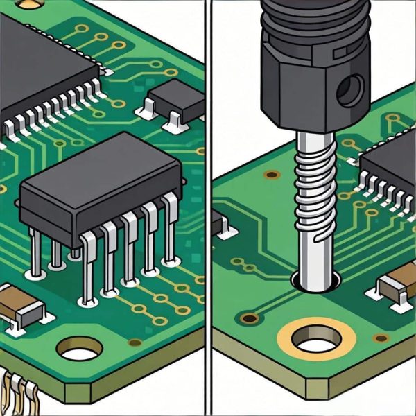
This guide compares USB-C SMT vs through-hole connectors across seven engineering parameters — mechanical strength, PCB footprint, signal integrity, assembly process, plug-in stress, cost, and reliability — so you can specify the right mounting technology for your application.
Need a USB-C Connector for Your PCB?
Vistar Electronics supplies USB-C receptacles in SMT-only, through-hole, and hybrid SMT+THT configurations. 6-pin through 24-pin, USB 2.0 through USB4 Gen 3, with up to 5A current rating and 10,000 mating cycles. RoHS 3 & REACH compliant. MOQ 1,000 pcs. Free samples available.
What Is a USB-C SMT Connector?
A USB-C SMT connector is mounted directly onto the surface of the PCB. Its signal contacts and shell tabs are soldered to surface pads using reflow soldering. No leads pass through the board.
SMT USB-C connectors enable high-density layouts and are compatible with fully automated pick-and-place assembly. They are the standard choice for compact consumer electronics and high-volume production.
However, the mechanical retention of an SMT-only connector depends entirely on the solder fillets between the connector terminals and the PCB pads. Under repeated cable insertion and extraction, these joints can experience significant stress.
For a detailed example of a high-reliability SMT-only design, see the Vertical USB-C Connector 24 Pin SMT Straight — a full-featured USB4 receptacle rated for 10,000 mating cycles.
What Is a USB-C Through-Hole Connector?
A USB-C through-hole connector uses leads that pass through drilled holes in the PCB and are soldered on the opposite side. This creates a physical anchor that resists mechanical stress far better than surface solder joints alone.
Through-hole USB-C connectors are common in applications where the port will be subjected to frequent plugging and unplugging, vibration, or high insertion forces. Industrial equipment, docking stations, and test instruments frequently specify through-hole mounting for this reason.
The trade-off is board space. Through-hole leads require drilled holes, consume routing area on both sides of the board, and are not compatible with bottom-side SMT components in the immediate vicinity.
For a hybrid approach that combines SMT signal contacts with through-hole retention tabs, see the 24-Pin USB-C Plug Vertical SMT Through-Hole connector.
USB-C SMT vs Through-Hole: Technical Comparison
| Factor | SMT | Through-Hole | Hybrid (SMT + THT) |
|---|---|---|---|
| Mounting | Surface pads only | Leads through PCB | SMT signal + THT retention |
| Mechanical Strength | Moderate | Excellent | Excellent |
| PCB Space | High density | Lower density | Moderate |
| Assembly | Fully automated reflow | Wave / selective solder | Mixed process |
| Signal Integrity | Low parasitics | Higher parasitics | Low parasitics (signal) |
| Plug-in Stress | Limited cycles | High cycles | High cycles |
| Cost (high volume) | Lower | Higher | Moderate |
| Rework | Difficult | Easy | Mixed |
| Best For | Compact devices | External ports | High-reliability designs |
1. Mechanical Strength and Plug-In Stress
This is the single most important difference between SMT and through-hole USB-C connectors.
Through-hole connections can withstand forces up to 10 times greater than equivalent SMT joints, according to PCB assembly industry data. This is not a marginal difference. It is the difference between a port that survives 10,000 insertions and one that develops micro-cracks after 2,000.
The reason is structural. A through-hole lead passes through the board and is soldered on the opposite side, creating a mechanical anchor that distributes insertion force across the PCB thickness. An SMT joint relies on the adhesion between the solder fillet and the surface pad, which is vulnerable to shear and peel stress.
For USB-C ports that will be mated frequently — docking stations, charging ports, industrial equipment — through-hole or hybrid mounting is the appropriate choice.
For a more detailed analysis of mechanical stress factors, see the USB-C Mid Mount vs Top Mount comparison.
2. PCB Footprint and Board Space
SMT USB-C connectors free up board space. The absence of through-hole leads means the area beneath and around the connector can be used for routing or bottom-side components.
Through-hole connectors consume routing resources. Each lead requires a drilled hole, and the solder side of the board must remain accessible for wave or selective soldering.
Hybrid connectors occupy a middle ground. The signal contacts are SMT, so high-speed routing remains clean. The through-hole retention tabs are typically limited to the shell or mounting posts, minimizing the routing penalty.
Footprint verification is mandatory. Always request the manufacturer’s recommended PCB footprint before releasing the board. A generic USB-C footprint will not match the specific shell geometry, retention tab positions, and keep-out requirements of every connector.
For USB-C PCB layout guidance specific to high-speed designs, see How to Ensure Signal Integrity in PCB Layout for USB C PCB Connector.
3. Signal Integrity at High Data Rates
At USB 3.2 Gen 2 (10 Gbps) and USB4 (40 Gbps), signal integrity becomes a primary design constraint. The connector mounting technology affects the parasitic characteristics of the signal path.
SMT contacts have lower parasitic inductance than through-hole leads. SMT connectors typically exhibit around 1.0 nH of parasitic inductance, compared to 10–15 nH for through-hole leads. At multi-gigabit data rates, this difference can affect insertion loss and return loss.
This does not mean through-hole USB-C connectors cannot support high-speed data. It means the signal path must be designed more carefully. A well-designed through-hole connector with controlled impedance and proper PCB routing can meet USB 3.2 and USB4 requirements — but the margin for error is smaller.
For hybrid connectors, the signal contacts are SMT, so the high-speed path benefits from low parasitics. The through-hole retention tabs carry mechanical load, not high-speed signals. This is one reason hybrid mounting has become the preferred architecture for high-reliability USB-C designs.
The official USB Type-C specification defines the mechanical and electrical requirements for both connector types. For reference, see the USB-IF USB Type-C Connector and Cable Assemblies Compliance Document.
4. Assembly Process and Manufacturing
SMT-only assembly is fast and highly automated. Pick-and-place machines can mount thousands of components per hour, and the entire board goes through a single reflow cycle. For high-volume consumer electronics, this is the lowest-cost path.
Through-hole assembly requires a separate process step. Wave soldering, selective soldering, or hand soldering is used after the SMT reflow is complete. This adds time and cost. However, many modern boards use a mixed-technology approach: SMT for the majority of components, and selective soldering for the through-hole connector leads.
Hybrid assembly combines both. The SMT contacts are reflowed with the rest of the board. The through-hole retention tabs are then selectively soldered. This adds process complexity but delivers the mechanical performance required for external ports.
When specifying a hybrid connector, confirm that the assembly house has selective soldering capability and that the connector’s reflow profile is compatible with the board’s thermal requirements.
5. Reliability and Thermal Cycling
SMT solder joints are more susceptible to thermal cycling stress than through-hole joints. As the board heats and cools, the coefficient of thermal expansion (CTE) mismatch between the connector housing, the solder, and the PCB can cause micro-cracks in the solder fillet.
Through-hole joints are more resilient because the solder fills the barrel of the drilled hole, creating a larger cross-section that distributes thermal stress. For applications with wide operating temperature ranges — industrial, automotive, outdoor equipment — this durability advantage is significant.
For consumer electronics with moderate temperature cycling, a well-designed SMT joint is adequate. The key variables are the solder alloy, the pad geometry, and the thermal profile of the assembly process.
6. Cost and High-Volume Production
Connector unit price is not the same as total landed cost.
An SMT connector may have a lower unit price and lower assembly cost. A through-hole connector may cost more per piece and require an additional soldering step. But if the through-hole connector eliminates field failures caused by cracked solder joints, the total cost may be lower.
Consider the full cost equation:
- Connector unit price
- PCB fabrication (drilled holes add cost)
- Assembly process (wave/selective solder adds cost)
- Rework and repair cost
- Field failure rate
- Warranty claims
For high-volume consumer products where the port is used primarily for charging and occasional data transfer, SMT is often the economically rational choice. For industrial equipment where the port is mated daily for years, the mechanical reliability of through-hole or hybrid mounting justifies the additional cost.
7. Application Selection: Which Should You Choose?
| Application | Recommended Mounting | Reason |
|---|---|---|
| Consumer smartphone | SMT | Compact, high-volume, moderate port use |
| Laptop charging port | Hybrid or THT | Frequent plugging, durability critical |
| Docking station | Hybrid or THT | Daily mating cycles, external port |
| Industrial equipment | THT or Hybrid | Vibration, high insertion force |
| Development board | SMT or THT | Depends on port usage frequency |
| Medical device | Hybrid | Reliability, cleanliness, frequent use |
| USB hub | SMT | Internal port, low mechanical stress |
| Portable power bank | SMT | Compact, moderate usage |
| Test instrument | THT | Repeated connections, reliability required |
The decision should be made at the same time as the PCB and enclosure architecture — not after the board has been routed.
How to Select a USB-C Connector for Production
Before requesting a quotation, define these parameters:
- Mounting technology — SMT, through-hole, or hybrid
- Pin count — 6, 12, 14, 16, or 24 pins
- Data rate — USB 2.0, USB 3.2 Gen 1/Gen 2, or USB4
- Current rating — 3A or 5A (VBUS)
- Mating cycles — 5,000 or 10,000
- PCB thickness — standard or thin board
- Operating temperature — commercial or industrial range
- Enclosure clearance — available Z-height
- Assembly process — reflow, wave, selective, or mixed
- Annual volume — for pricing and packaging
For a detailed reference on pin configurations and their electrical roles, see USB-C Connector Pinout Explained: 24P to 6P Complete Guide.
Why Choose Vistar Electronics for USB-C Connectors
Vistar Electronics manufactures USB-C receptacles in SMT-only, through-hole, and hybrid SMT+THT configurations. The range covers 6-pin through 24-pin designs, USB 2.0 through USB4 Gen 3, with current ratings up to 5A and mating cycle ratings up to 10,000.
Key capabilities:
- Hybrid SMT+THT USB-C connectors combining low-parasitic SMT signal contacts with through-hole mechanical retention
- USB4 40 Gbps and USB 3.2 Gen 2 designs with gold-plated contacts and stainless steel shells
- 10,000 mating cycle rating on full-featured receptacles
- ISO 9001:2015 manufacturing, RoHS 3 and REACH compliance
- OEM/ODM customization: pin count, mounting style, plating, packaging
- Free engineering samples and 2D/3D mechanical drawings
Browse the full USB-C connector range or contact the engineering team to discuss your specific mounting and signal integrity requirements.
Frequently Asked Questions
What is the difference between USB-C SMT and through-hole connectors?
SMT USB-C connectors are mounted on the PCB surface using reflow-soldered pads. Through-hole USB-C connectors have leads that pass through drilled holes and are soldered on the opposite side, providing greater mechanical strength for repeated plugging and high-stress applications.
Which is stronger, USB-C SMT or through-hole?
Through-hole connections are significantly stronger. Industry data shows through-hole joints can withstand forces up to 10 times greater than equivalent SMT joints, making them preferable for external ports that endure frequent insertion and extraction.
Can USB-C SMT connectors support USB4 40 Gbps?
Yes. SMT connectors have lower parasitic inductance (approximately 1.0 nH versus 10–15 nH for through-hole), which is advantageous for high-speed signaling. However, signal integrity also depends on PCB routing, impedance control, and the specific connector construction. A well-designed SMT or hybrid connector can support USB4 when properly implemented.
What is a hybrid USB-C connector?
A hybrid USB-C connector combines SMT signal contacts with through-hole retention tabs. The SMT contacts carry high-speed signals with low parasitics, while the through-hole tabs provide mechanical strength for the external port. This architecture is common in high-reliability USB-C designs.
Are through-hole USB-C connectors obsolete?
No. Through-hole and hybrid connectors remain the standard choice for industrial equipment, docking stations, test instruments, and any application where the USB-C port is mated frequently or subjected to mechanical stress.
Which mounting type should I choose for a docking station?
Hybrid or through-hole. Docking stations typically have USB-C ports that are plugged and unplugged daily, requiring high mechanical durability. Hybrid connectors provide the signal integrity of SMT with the mechanical retention of through-hole.
Do through-hole USB-C connectors cost more than SMT?
Through-hole connectors may have a higher unit price and require an additional soldering process step. However, the total cost should be evaluated against the cost of field failures and warranty claims if an SMT joint fails under mechanical stress.
What PCB footprint should I use for a USB-C connector?
Always use the manufacturer’s recommended PCB footprint. A generic USB-C footprint will not account for the specific shell geometry, retention tab positions, keep-out area, and solder pad dimensions of the selected connector. Request the 2D drawing and 3D STEP model before releasing the board.
Need a USB-C Connector Matched to Your PCB?
Vistar Electronics supplies USB-C receptacles in SMT-only, through-hole, and hybrid configurations. 6-pin through 24-pin, USB 2.0 through USB4 Gen 3, with up to 5A current rating and 10,000 mating cycles. RoHS 3 & REACH compliant. MOQ 1,000 pcs. Free samples available.
Conclusion: Choose the Mounting Technology Before You Lock the PCB
The choice between USB-C SMT vs through-hole is not a simple matter of cost or convention. It is a mechanical and electrical decision that affects the durability, signal integrity, assembly process, and total cost of the product.
SMT connectors are the right choice for compact, high-volume consumer devices where the port is used for moderate charging and data transfer. Through-hole connectors are the right choice for external ports that endure repeated mating and mechanical stress. Hybrid connectors offer the best of both: SMT signal integrity with through-hole mechanical strength.
The key is to make the decision early — before the PCB layout is finalized and before the enclosure design is locked. Request the connector’s mechanical drawing and recommended footprint before committing to a production run. Test a physical sample to validate mating force, cable fit, and mechanical clearance. And specify the mounting technology, pin count, data rate, and current rating together, not as separate decisions.
Vistar Electronics supplies USB-C connectors across SMT, through-hole, and hybrid mounting configurations, allowing engineers to compare mechanical and electrical performance before selecting a part. For projects where port durability or high-speed signal integrity is critical, requesting samples and mechanical drawings before the PCB is released is the most efficient way to avoid avoidable redesigns.


