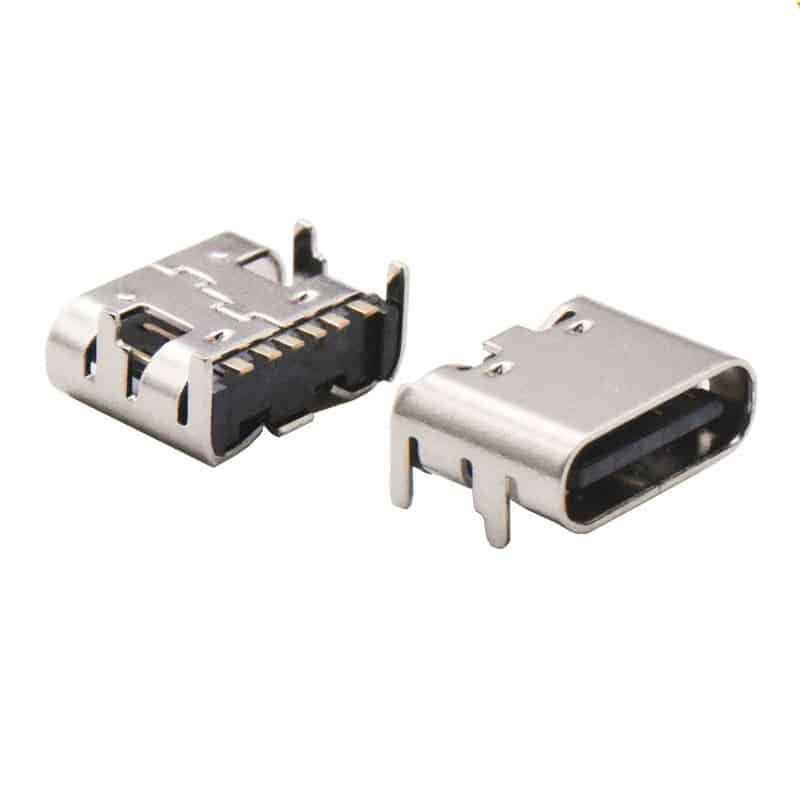
The design of the USB-C Female Connector Pinout employs a centrally symmetrical structure, which is the foundation for its reversible plugging feature. Below is a detailed pin definition and functional explanation.
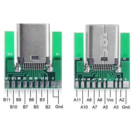
24-Pin USB-C Female Connector Pinout
The following table details the functions of each pin in a standard 24-pin USB-C female receptacle. The pin arrangement is symmetrical along the central axis (Row A and Row B).

| Pin Number (Row A) | Pin Number (Row B) | Pin Name | Function Description |
|---|---|---|---|
| A1 | B12 | GND | Signal ground. |
| A2 | B11 | SSTXp1 / SSRXp1 | SuperSpeed differential pair #1: Transmit Positive (TX+) / Receive Positive (RX+). The function depends on cable orientation and negotiated mode. |
| A3 | B10 | SSTXn1 / SSRXn1 | SuperSpeed differential pair #1: Transmit Negative (TX-) / Receive Negative (RX-). |
| A4, A9 | B4, B9 | VBUS | Bus power. Supplies power to the device. Multiple pins are used to support higher currents. |
| A5 | B5 | CC1 / CC2 | Configuration Channel. Used for attachment detection, orientation detection (flip identification), power role (Source/Sink) negotiation, and USB Power Delivery (PD) communication. |
| A6, A7 | B6, B7 | Dp1, Dn1 / Dp2, Dn2 | USB 2.0 differential pair. Only one pair is electrically active; the redundancy supports reversible plugging. |
| A8 | B8 | SBU1 / SBU2 | Sideband Use pins. Primarily used for auxiliary signals in Alternate Modes (e.g., DisplayPort Alternate Mode for AUX channel). |
| A10, A11 | B2, B3 | SSRXp2, SSRXn2 / SSTXp2, SSTXn2 | SuperSpeed differential pair #2: Receive (RX) / Transmit (TX). Function depends on orientation. |
| A12 | B1 | GND | Signal ground. |
Key Pin Functions Explained in Detail
Understanding the following key pins is crucial for design and troubleshooting:
- VBUS and GND:
- The USB-C interface includes 4 VBUS pins and 4 GND pins. This multi-pin parallel design is intended to support high-current transmission, capable of delivering up to 240W (48V/5A) as per the USB PD 3.1 specification. The default voltage is 5V.
- Design Tip: In high-power applications, ensure all VBUS and GND pins on the PCB are properly connected with adequate trace/pour width to handle the intended current without excessive voltage drop or heating.
- CC (Configuration Channel) Pins:
- These are the “intelligent core” of the USB-C interface. The CC1 and CC2 pins manage attachment detection, plug orientation (flip) detection, power role determination (Source/DFP or Sink/UFP), and USB Power Delivery (PD) protocol communication.
- When a cable contains an E-Marker chip, one of the CC pins is repurposed as VCONN to power that chip.
- Design Tip: The CC pins on a Downstream Facing Port (DFP, like a host or charger) typically require pull-up resistors (Rp), while an Upstream Facing Port (UFP, like a device) requires pull-down resistors (Rd). The values are defined by the USB Type-C specification and are critical for proper operation.
- High-Speed Differential Pairs (SSTX/SSRX):
- These are used to support USB 3.2/4 and other high-speed data protocols, enabling speeds up to 40 Gbps (USB4).
- Due to the symmetrical interface, only one TX pair and one RX pair are active for communication in a given orientation. The specific pairs used are swapped when the plug is flipped.
- Design Tip: These pairs require strict 90-ohm differential impedance control, length matching, and a continuous reference ground plane in the PCB layout to preserve signal integrity.
- USB 2.0 Differential Pair (D+/D-):
- Used for USB 2.0 speed data transfer (up to 480 Mbps).
- The receptacle has two physical pairs, but they are internally connected; only one logical pair is used.
- SBU (Sideband Use) Pins:
- Used primarily in Alternate Modes. For example, in DisplayPort Alt Mode, SBU1 and SBU2 carry the AUX (auxiliary) channel signals for display control (DDC/CI) and other functions.
Simplified Pin Configurations
For cost-sensitive applications that do not require full functionality, simplified versions exist:
- 16-Pin (often called 12-pin) Type:
- This version removes the TX/RX differential pairs used for USB 3.0+ high-speed data (A2, A3, A10, A11, B2, B3, B10, B11).
- It retains the USB 2.0 pairs, CC, SBU, and power pins. Therefore, it still supports USB PD fast charging, audio accessory mode, and debug accessory mode, but does not support SuperSpeed (USB 3.0+) data transfer.
- Typical Use: Keyboards, mice, basic chargers, low-speed data devices where cost and simplicity are prioritized over speed.
- 6-Pin Type:
- This is the most minimal version, retaining only VBUS, GND, CC1, and CC2 pins.
- It is used for charging only and has no data transfer capability whatsoever. The presence of CC pins allows it to support USB PD fast charging protocols.
- Typical Use: Dedicated power banks, simple LED lamps, fans, and other appliances that only need to draw power.
Design Considerations and Summary of Core Points
Key Takeaways:
- The core of the USB-C female receptacle pin design is its symmetry, enabling reversible plugging.
- The CC pins are the key to intelligent power negotiation, role detection, and mode configuration.
- The interface can be selected based on needs: Full-featured (24-pin), USB 2.0 only (16-pin), or Charge-only (6-pin).
Expanded Design Notes:
- Pin 1 Identification: On the receptacle, Pin A1 is typically marked on the housing or can be identified by its position relative to the notch in the center tongue.
- PCB Footprint Symmetry: When designing the PCB footprint, note that the A-row and B-row pads are mirror images. Many connector datasheets provide a recommended footprint that automatically handles this symmetry.
- Shield Connection: The metal shell of the connector must be securely connected to the chassis ground or shield ground on the PCB. This is crucial for EMI/EMC performance and is often done via grounding clips or pads on the connector’s sides.
This information should aid in better design and troubleshooting. If you require further details on specific aspects like Alternate Mode pin mapping or the detailed Guide to USB-C Pinout and Features, feel free to ask.