Complete guide to RJ45 pinout and wiring. Compare T568A vs T568B standards, color codes, straight-through vs crossover cables, and PCB design considerations for Ethernet connectors.
You are designing a new networking product. The PCB layout is nearly complete, and the RJ45 jack footprint is placed. Then the question comes: Which wiring standard should I use — T568A or T568B?
This is one of the most common questions in Ethernet connector design. The two standards look nearly identical, perform exactly the same electrically, and both are officially recognized by the TIA/EIA. Yet the choice matters — for compatibility, for customer expectations, and for avoiding costly field failures.
This guide covers everything you need to know about RJ45 pinout and wiring: the T568A and T568B standards, color codes, cable types, PCB design considerations, and how to choose the right standard for your application.
Internal link: For a complete overview of RJ45 connector options, see our RJ45 Modular Jack Product Center .
What Is an RJ45 Connector?
An RJ45 connector is an 8-position, 8-contact (8P8C) modular connector commonly used for Ethernet networking. It is the physical interface that terminates twisted-pair Ethernet cables and connects devices like computers, routers, switches, and industrial equipment to a network.
The RJ45 connector has eight pins, each corresponding to a specific wire in the Ethernet cable. The arrangement of these wires is defined by the T568A and T568B wiring standards.
Key characteristics:
- 8 pins (8P8C configuration)
- Locking tab for secure connection
- Twisted-pair termination for signal integrity
- Supports Cat5e, Cat6, and Cat6a cabling
- Shielded and unshielded variants available
Internal link: Explore our RJ45 Modular Jacks —available in shielded and unshielded configurations, multiple mounting styles, and Cat5e/Cat6/Cat6a support.
T568A vs T568B: The Two Wiring Standards
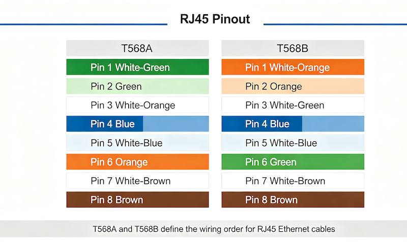
The TIA/EIA-568 standard defines two wiring schemes for RJ45 connectors: T568A and T568B. Both are officially recognized and perform identically from an electrical standpoint.
The only difference between T568A and T568B is the orange and green wire pairs are swapped on pins 1, 2, 3, and 6.
T568A Pinout
| Pin | Wire Color | Pair |
|---|---|---|
| 1 | White/Green | Pair 3 |
| 2 | Green | Pair 3 |
| 3 | White/Orange | Pair 2 |
| 4 | Blue | Pair 1 |
| 5 | White/Blue | Pair 1 |
| 6 | Orange | Pair 2 |
| 7 | White/Brown | Pair 4 |
| 8 | Brown | Pair 4 |
Signal assignment (T568A):
- Pins 1 & 2: Receive (Rx+ / Rx-)
- Pins 3 & 6: Transmit (Tx+ / Tx-)
- Pins 4 & 5: Unused / Backup / Bidirectional Data A
- Pins 7 & 8: Unused / Backup / Bidirectional Data B
T568B Pinout
| Pin | Wire Color | Pair |
|---|---|---|
| 1 | White/Orange | Pair 2 |
| 2 | Orange | Pair 2 |
| 3 | White/Green | Pair 3 |
| 4 | Blue | Pair 1 |
| 5 | White/Blue | Pair 1 |
| 6 | Green | Pair 3 |
| 7 | White/Brown | Pair 4 |
| 8 | Brown | Pair 4 |
Signal assignment (T568B):
- Pins 1 & 2: Transmit (Tx+ / Tx-)
- Pins 3 & 6: Receive (Rx+ / Rx-)
- Pins 4 & 5: Unused / Backup / Bidirectional Data A
- Pins 7 & 8: Unused / Backup / Bidirectional Data B
External link: For a visual reference, see FlexRadio’s RJ45 pinout diagrams for both T568A and T568B.
T568A vs T568B: Side-by-Side Comparison
| Feature | T568A | T568B |
|---|---|---|
| Pin 1 | White/Green | White/Orange |
| Pin 2 | Green | Orange |
| Pin 3 | White/Orange | White/Green |
| Pin 4 | Blue | Blue |
| Pin 5 | White/Blue | White/Blue |
| Pin 6 | Orange | Green |
| Pin 7 | White/Brown | White/Brown |
| Pin 8 | Brown | Brown |
| Transmit Pair | Pins 3 & 6 | Pins 1 & 2 |
| Receive Pair | Pins 1 & 2 | Pins 3 & 6 |
| Electrical Performance | Identical | Identical |
| Common Use | Government, older installations | Commercial, home networks |
External link: For a detailed breakdown of the differences, see NetAlly’s T568A vs T568B comparison .
Which Standard Should You Use?
Choose T568B if:
- Most commercial installations in the US and UK use T568B
- You are designing for the general market — T568B is the most widely used standard
- Your customers expect standard commercial wiring — most off-the-shelf equipment is wired to T568B
Choose T568A if:
- Government or federal installations require T568A
- You need backward compatibility with USOC telephone wiring
- Your customer specifies T568A — primarily used in government and some European installations
The Bottom Line
For most applications, T568B is the recommended choice. It is the de facto standard for commercial and home networks in North America and is widely adopted globally.
However, both standards work equally well. The key is consistency — use the same standard on both ends of a straight-through cable, and document which standard you are using.
Internal link: Our RJ45 Modular Jacks are designed to be compatible with both T568A and T568B wiring standards, ensuring they can be used in any standard network installation globally.
Straight-Through vs Crossover Cables
Straight-Through Cable
- Both ends use the same standard (T568B to T568B, or T568A to T568A)
- Used for connecting different device types: PC to switch, router to switch
- Most common type of Ethernet cable
Crossover Cable
- One end uses T568A, the other end uses T568B
- Used for connecting same device types: PC to PC, switch to switch
- Less common today — most modern devices support Auto-MDIX (automatic crossover detection)
External link: For more on cable types and wiring, see JiaxunZG’s RJ45 wiring guide .
Cable Types and RJ45 Compatibility
| Cable Type | Frequency | Speed | Typical Use |
|---|---|---|---|
| Cat5e | 100 MHz | 1 Gbps | Home and office networks |
| Cat6 | 250 MHz | 1–10 Gbps | High-speed LAN |
| Cat6A | 500 MHz | 10 Gbps | Data centers |
| Cat7 | 600+ MHz | 10 Gbps | Industrial / special cases |
All of these cable types use the same RJ45 pinout — the wiring diagram is identical regardless of cable category. The difference is in cable construction, shielding, and performance.
Internal link: We offer RJ45 jacks optimized for Cat5e, Cat6, and Cat6a cabling.
PCB Design Considerations for RJ45 Connectors
When designing a PCB with an RJ45 jack, several factors are critical for signal integrity and performance.
Differential Pair Routing
The most important design principle is ensuring that differential signal pairs are correctly paired, routed closely together, and strictly length-matched to meet impedance control and signal integrity requirements.
Key signal pairs:
- Pins 1 & 2: Transmit pair (Tx+ / Tx-) — route as a 100Ω differential pair
- Pins 3 & 6: Receive pair (Rx+ / Rx-) — route as a 100Ω differential pair
- Pins 4 & 5: Bidirectional Data A (for Gigabit Ethernet)
- Pins 7 & 8: Bidirectional Data B (for Gigabit Ethernet)
PCB Footprint
The PCB footprint must clearly correspond to the RJ45 socket’s pin definitions (T568A or T568B). The pin numbering on the PCB should match the connector’s mechanical drawing.
Typical pin numbering (viewing the RJ45 socket from the mating face, latch down):
- Pins numbered 1 to 8 from left to right
10/100BASE-T vs Gigabit Ethernet
- 10/100BASE-T (Fast Ethernet): Uses only pins 1, 2, 3, and 6 (two pairs)
- Pins 1 & 2: Transmit (Tx)
- Pins 3 & 6: Receive (Rx)
- 1000BASE-T (Gigabit Ethernet): Uses all 8 pins (four pairs)
- All four pairs transmit and receive simultaneously (full-duplex)
Power over Ethernet (PoE)
If your design requires PoE, consider the additional current-carrying requirements:
- PoE (IEEE 802.3af): Up to 15.4W on pins 4,5 and 7,8
- PoE+ (IEEE 802.3at): Up to 30W
- PoE++ (IEEE 802.3bt): Up to 60W or 100W
Ensure the RJ45 jack and PCB traces are rated for the required current.
Mounting Styles
RJ45 jacks are available in multiple PCB mounting configurations:
| Mounting Style | Best For |
|---|---|
| Right-Angle SMT | Edge-mounted designs, high-volume assembly |
| Right-Angle DIP | Edge-mounted designs, maximum mechanical strength |
| Vertical SMT/DIP | Top-entry designs, space-constrained layouts |
| Mid-Mount | Ultra-low-profile designs |
Internal link: Explore our RJ45 Modular Jacks with multiple mounting options —including right-angle, vertical, SMT, DIP, and mid-mount configurations.
Common Wiring Mistakes
Mistake 1: Mixing T568A and T568B on a straight-through cable
Using T568A on one end and T568B on the other creates a crossover cable — which may not work with devices that do not support Auto-MDIX.
Solution: Use the same standard on both ends for straight-through cables.
Mistake 2: Incorrect pin assignment on PCB
A mirrored footprint or incorrect pin numbering can cause the entire board run to fail.
Solution: Always verify the PCB footprint against the connector’s mechanical drawing.
Mistake 3: Not maintaining differential pair integrity
Routing Tx and Rx pairs separately or with mismatched lengths can cause signal reflections and failed Ethernet compliance testing.
Solution: Route each differential pair together, length-matched, with controlled 100Ω impedance.
Mistake 4: Forgetting about PoE current requirements
PCB traces that are too thin for PoE current can overheat and fail.
Solution: Calculate trace width for the required current and use appropriate copper weight.
Mistake 5: Overlooking shielding requirements
In industrial or high-EMI environments, unshielded jacks may allow interference to corrupt signals.
Solution: Specify shielded RJ45 jacks for industrial, automotive, or high-density applications.
Frequently Asked Questions
What is the difference between T568A and T568B?
The only difference is that the orange and green wire pairs are swapped on pins 1, 2, 3, and 6. T568A has green on pins 1 & 2 and orange on pins 3 & 6. T568B has orange on pins 1 & 2 and green on pins 3 & 6.
Which standard should I use: T568A or T568B?
For most commercial and home applications, T568B is recommended. It is the most widely used standard in North America and is the default for most off-the-shelf equipment. Use T568A for government installations or when specified by the customer.
Do T568A and T568B perform differently?
No. Both standards perform identically from an electrical standpoint. The difference is purely in the color arrangement.
What is a crossover cable?
A crossover cable has T568A on one end and T568B on the other. It is used to connect two devices of the same type (e.g., PC to PC). Most modern devices support Auto-MDIX, which automatically detects and corrects for crossover cables.
What is the difference between RJ45 and 8P8C?
They are often used interchangeably. RJ45 technically refers to a specific wiring standard (8P8C with a keyed interface), but in practice, the terms are used synonymously for the 8-position modular connector used in Ethernet.
What pins does 10/100 Ethernet use?
10/100BASE-T uses only pins 1, 2, 3, and 6 — two pairs for transmit and receive.
What pins does Gigabit Ethernet use?
1000BASE-T uses all 8 pins — four pairs, all transmitting and receiving simultaneously.
Do your RJ45 jacks support both T568A and T568B?
Yes. Our RJ45 modular jacks are designed to be compatible with both T568A and T568B wiring standards, ensuring they can be used in any standard network installation globally.
RJ45 Modular Jacks from Vistar Electronics
At Vistar Electronics, we understand the nuances of RJ45 connector design and PCB integration. Our RJ45 modular jack portfolio includes:
- Standardized 8P8C design — fully compatible with standard RJ45 plugs
- High-speed data support — engineered for Gigabit Ethernet and beyond
- Secure locking mechanism — robust locking tab design prevents accidental disconnections
- Multiple mounting options — SMT, DIP, right-angle, vertical, and mid-mount configurations
- Shielding options — shielded (for EMI/RFI protection) and unshielded versions
- Gold-plated contacts — superior conductivity and oxidation resistance
- Compatibility — supports Cat5e, Cat6, and Cat6a cabling
- Compliance — compatible with both T568A and T568B wiring standards
Whether you are designing a networking switch, an industrial controller, or a consumer electronics device, the right RJ45 connector starts with understanding the pinout and wiring standard requirements. We can help you specify it, source it, and integrate it.
Internal link: Browse our full range of RJ45 Modular Jacks .
For technical specifications, samples, or application support, contact the Vistar Electronics engineering team.