Detector Switch Selection Guide. Covers actuators, ratings, sealing & SMT specs for consumer electronics and industrial use.
The Silent Failure That Kills Product Launches
Your IoT sensor node passed every bench test. The firmware was solid, the RF link was clean, and the battery life hit the spec. Then the first field units came back with a bizarre fault: the device randomly reported “cover open” when the enclosure was sealed shut.
The culprit was a detector switch. Specifically, a pin-plunger variant with an operating force of 500 gf that was supposed to detect a 200-gram plastic battery door. The door’s own weight never fully depressed the plunger, so the contact bounced between open and closed states as the device vibrated in a user’s pocket. A $0.15 part torpedoed a six-figure product line.
This is not a rare story. Detector switches are among the most under-specified components in modern electronics, precisely because they appear so simple. They are not. The gap between a switch that works on paper and one that survives a million cycles in the field is where most designs fail. This guide closes that gap.
What a Detector Switch Actually Is (And What It Is Not)
A detector switch is a mechanically actuated electrical component that converts physical displacement into a discrete on/off signal. Unlike general-purpose pushbuttons meant for human interaction, detector switches are engineered for automated position sensing—detecting whether a door is closed, a tray is inserted, or a slider has reached its end position.
The critical distinction is travel. A detector switch operates over a very short stroke—typically 0.3 mm to 3.2 mm—with precisely defined pre-travel, operating point, and over-travel zones. This tight mechanical envelope makes them ideal for space-constrained applications where a micro switch would be too tall and a limit switch would be absurdly oversized.
They are not proximity sensors. They require physical contact. They are not tactile switches. They are not designed for finger actuation. Misunderstanding this fundamental identity is the root cause of most detector switch failures.
Core Parameters That Define Detector Switch Performance
Operating Force and Release Force
Operating force (OF) is the minimum external load needed to snap the internal contacts closed. Release force is the load at which the contacts spring back open. The delta between these two values is hysteresis, and it matters enormously for vibration immunity.
Typical detector switches range from 50 gf (ultra-sensitive) to 500 gf (heavy-duty). For battery door detection in handheld devices, 130–160 gf is the sweet spot—light enough for a plastic tab to actuate reliably, heavy enough to ignore casual bumps. For industrial cassette detection, 300–500 gf prevents false triggers from machine vibration.
Critical rule: The actuating mechanism in your product must deliver at least 120% of the rated operating force at the switch contact point, accounting for tolerance stack-up and material creep over the product lifetime.
Travel and Over-Travel
Pre-travel is the distance from rest to the operating point. Over-travel is the distance the actuator can move beyond the operating point without damaging the switch. A healthy over-travel margin—typically 0.5 mm to 2.0 mm—is your insurance policy against tolerance drift and mechanical wear.
Panasonic’s ESE31 series, for example, offers 3.2 mm full travel with 2.15 mm operating distance, leaving substantial over-travel for tolerance absorption. The ESE23 bidirectional variant delivers 2.2 mm full travel with a 1.5 mm operating point—tighter, but necessary when PCB height is restricted to 1.5 mm.
Electrical Rating and Contact Material
Detector switches for consumer electronics typically carry ratings like 50 µA at 3 VDC minimum to 10 mA at 5 VDC maximum. This is signal-level territory, not power switching. Attempting to drive a relay coil or LED directly through a detector switch will weld the contacts shut within weeks.
| Contact Material | Best For | Avoid When |
|---|---|---|
| Gold-plated | Low-level signals (<20V, <100mA), humid environments, long-term reliability | High-current loads, cost-sensitive high-volume |
| Silver-plated | Higher current, cost-optimized designs, indoor dry environments | Low-voltage signal circuits, corrosive atmospheres |
Gold does not oxidize, so contact resistance stays stable at microvolt signal levels. Silver offers superior bulk conductivity but tarnishes; in low-current circuits, that tarnish layer becomes an insulator. For detector switches handling logic signals to an MCU, gold is almost always the correct choice. For power-path detection in appliances, silver is defensible.
Contact Resistance and Insulation Resistance
Initial contact resistance for quality detector switches should be below 500 mΩ, with premium variants hitting 100 mΩ or less. After operating life testing, this may degrade to 1 Ω maximum—a threshold that still works for digital logic but can corrupt analog measurements.
Insulation resistance must exceed 100 MΩ at 100 VDC. Dielectric withstanding voltage is typically 100 VAC for 1 minute. These numbers are modest compared to power relays, but they are more than adequate for the signal-level applications where detector switches live.
Mechanical and Electrical Life
Life ratings split into two categories:
- Mechanical life: Cycles without electrical load. Ranges from 50,000 to 1,000,000 cycles depending on series and operating force. Lower-force switches generally live longer because the internal spring experiences less stress.
- Electrical life: Cycles under rated load. Always shorter than mechanical life, sometimes by an order of magnitude. A switch rated for 1,000,000 mechanical cycles may only survive 100,000 electrical cycles at full load.
For a battery door that gets opened twice a day, 50,000 electrical cycles translates to 68 years. For a printer cartridge detection mechanism that cycles every print job, 100,000 cycles might last two years. Do the math before you spec.
Operating Temperature Range
Standard consumer-grade detector switches operate from −10°C to +60°C or −25°C to +80°C. Automotive-qualified variants extend to −40°C to +85°C or even +125°C for under-hood applications.
The temperature rating is not just about whether the plastic housing melts. At low temperatures, lubricants stiffen and operating force increases. At high temperatures, contact resistance rises as plating diffusion accelerates. If your product sees thermal cycling—think dashboard-mounted GPS units—spec the automotive grade even for consumer applications.
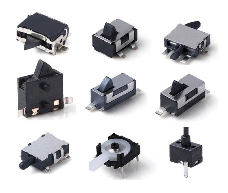
Actuator Types: Matching Mechanism to Motion

The actuator is the physical interface between your product’s moving part and the switch’s internal mechanism. Choosing wrong here is like putting a round peg in a square hole—it might work once, but it will fail repeatedly.
Pin Plunger
A straight vertical post that translates linear motion directly into switch actuation. Best for applications where a flat surface presses squarely against the switch. Operating force is typically the highest among actuator types because the plunger acts directly on the snap mechanism with no leverage advantage.
Ideal for: Battery doors, cassette insertion detection, linear slide end-stops.
Trap: Requires a reliable mechanical stop. Without one, over-travel can crush the internal mechanism.
Hinge Lever
A lever arm pivots around a hinge, multiplying a small displacement at the tip into the required actuator travel at the base. This reduces operating force dramatically—sometimes to one-third of a pin plunger equivalent—and accommodates low-speed cams or dogs.
Ideal for: Rotary mechanisms, cam-followers, applications where the actuating surface moves in an arc.
Simulated Roller Lever
The tip of a hinge lever is bent into a semi-circular profile, creating a simple roller effect. This reduces friction when the actuating surface slides across the lever tip during engagement.
Ideal for: Sliding trays, drawer detection, any application with lateral motion during actuation.
Leaf Lever
A flexible metal strip that uses its own elasticity to provide over-travel absorption. The “play” in the lever acts as a built-in tolerance buffer. Excellent resistance to freezing or binding in contaminated environments.
Ideal for: Outdoor equipment, agricultural machinery, applications with dust or debris.
Hinge Roller Lever
A hinge lever with a true rotating roller at the tip. Handles high-speed cams and dogs that would abrade a simulated roller. The roller converts sliding friction into rolling friction, extending both switch and cam life.
Ideal for: High-cycle industrial automation, conveyor systems, rapid indexing mechanisms.
Circuit Arrangements: SPST, SPDT, and Beyond
| Arrangement | Contacts | Use Case |
|---|---|---|
| SPST-NO | Single pole, normally open | Most common. Circuit completes when actuated. |
| SPST-NC | Single pole, normally closed | Safety-critical applications where “open” means fault. |
| SPDT | Single pole, double throw | One input, two outputs. Used for direction detection or redundant signaling. |
| Bidirectional (1P2T midpoint OFF) | Two throws, auto-return to center | Detects left/right or up/down position with one switch. |
The bidirectional midpoint-off variant is particularly elegant for joystick or dual-position detection. Panasonic’s ESE23 and ESE24 series use this architecture: push left, left circuit closes; release, both circuits open; push right, right circuit closes. One switch replaces two, saving PCB real estate and BOM cost.
Mounting and Packaging: SMT vs. THT vs. Panel Mount
Surface Mount (SMT)
The dominant format for modern consumer electronics. SMT detector switches sit flat on the PCB, secured by reflow soldered gullwing or J-bent terminals. Profiles as low as 1.5 mm enable ultra-thin designs.
Reflow considerations: Most SMT detector switches are compatible with standard lead-free reflow profiles—peak 235–250°C, time above liquidus 30–60 seconds. However, some series specify a maximum of 245°C for 5 seconds or 260°C for 3 seconds. Exceed these limits and the internal plastic actuator warps, shifting the operating point permanently.
Assembly reality: SMT detector switches are pick-and-place friendly and ship on embossed tape reels of 2,500 to 5,000 pieces. The challenge is not placement—it is ensuring the actuator does not get damaged by the placement nozzle pressure. Specify vacuum tooling with soft tips for ultra-low-profile variants.
Through-Hole (THT)
THT detector switches use PC pins that pass through drilled holes and are soldered by wave or selective soldering. They offer superior mechanical retention against insertion forces—critical for applications where the switch body itself is the bearing surface for a sliding mechanism.
Trade-off: THT consumes both sides of the PCB and blocks routing layers. In dense designs, this is often unacceptable.
Panel and Chassis Mount
Some detector switch families include snap-in or threaded variants that mount directly to a housing or panel, with flying leads or quick-connect terminals to the PCB. These isolate the switch from PCB flex and vibration, but add assembly steps and cost.
Sealed vs. Unsealed: The IP Rating Decision
Unsealed detector switches (typically IP40) are fine for indoor consumer electronics with controlled environments. They cost less, are smaller, and offer more actuator options.
Sealed variants (IP67) incorporate silicone gaskets and overmolded housings that withstand temporary immersion and dust ingress. The E-Switch TD1250 series, for example, achieves IP67 in an 8.25 mm × 5.25 mm package. ALPS SPVQ series offers IP6K7-rated variants for automotive under-hood use.
The cost reality: An IP67 detector switch costs roughly 35–50% more than its unsealed equivalent. But a field failure in a wearable or outdoor security camera costs infinitely more. If your product sees condensation, sweat, rain, or washdown, seal the switch.
Common Design Mistakes (And How to Avoid Them)
Mistake 1: Ignoring Tolerance Stack-Up
You design a battery door with 1.0 mm travel to actuate a switch with 0.5 mm operating point. Perfect, right? Wrong. Mold tolerance on the door is ±0.2 mm. PCB placement tolerance is ±0.15 mm. Switch height tolerance is ±0.1 mm. The stack-up is ±0.45 mm. Your 0.5 mm margin just evaporated.
Fix: Design for 150% of the switch’s total travel as the actuation mechanism’s guaranteed displacement. If the switch needs 0.5 mm, guarantee 0.75 mm minimum at worst-case tolerance.
Mistake 2: Specifying Operating Force Without Measuring the Actuator
A 160 gf switch sounds right for a plastic door. But if the door’s actuation tab is a flexible living hinge that deflects 0.3 mm under 50 gf, it will never generate 160 gf at the switch. The switch stays open, or chatters.
Fix: Model or prototype the actuation mechanism and measure the force it can deliver at the switch location. Then add 30% margin for material aging.
Mistake 3: Confusing Detector Switches with Tactile Switches
A tactile switch is designed for human finger pressure, with a crisp click and relatively high force. A detector switch is designed for machine-actuated position detection, with smooth travel and defined over-travel. Using a tactile switch as a detector invites contact bounce, inconsistent operating points, and premature wear.
Mistake 4: Overlooking Electrical Load
Running 100 mA through a switch rated for 10 mA maximum does not cause immediate failure. It causes gradual contact erosion that manifests as intermittent operation six months into the field. By then, your product is in 50,000 units and the recall cost is catastrophic.
Fix: Always design the detector switch into a signal path, not a power path. Use it to pull an MCU GPIO low, not to drive a relay coil directly.
Mistake 5: Assuming All “Detector Switches” Are Interchangeable
Two switches from different manufacturers may share the same footprint and look identical. But their operating force curves, contact bounce characteristics, and temperature drift can differ by 30% or more. Swapping suppliers without re-qualification is a recipe for field failures.
Detector Switch vs. Micro Switch vs. Limit Switch: When to Use What
| Parameter | Detector Switch | Micro Switch | Limit Switch |
|---|---|---|---|
| Typical Size | 3.5–8 mm footprint | 10–20 mm footprint | 30–60 mm footprint |
| Operating Force | 50–500 gf | 6–350 gf | 350 gf+ |
| Current Rating | µA to 100 mA | 0.1–5 A | 10–20+ A |
| Environmental Seal | Optional IP67 | Rare | Standard IP65+ |
| Mounting | SMT/THT/Panel | PCB or chassis | Chassis/panel only |
| Best For | Position detection in compact electronics | High-cycle control signals in appliances | Heavy-duty industrial end-of-travel |
Use a detector switch when space is tight, the load is signal-level, and the actuation is machine-driven. Use a micro switch when you need snap-action precision at moderate current in a slightly larger package. Use a limit switch when you are protecting industrial machinery from over-travel in a dirty, wet, high-vibration environment.
Practical Selection Framework
Follow this decision tree to narrow the field:
Step 1: Define the physical envelope.
What is the maximum height above the PCB? What is the available footprint? If height is under 2 mm, you are in ultra-low-profile detector switch territory.
Step 2: Characterize the actuation mechanism.
Is the motion linear, rotary, or sliding? What is the guaranteed displacement at the switch location? What force can the mechanism deliver?
Step 3: Determine the electrical requirements.
Is this a logic signal to an MCU, or does it need to switch power? What voltage and current? For logic signals, demand gold-plated contacts.
Step 4: Assess the environment.
Indoor clean room? IP40 is fine. Outdoor or wearable? IP67 is mandatory. Automotive under-hood? Specify AEC-Q200 compliant variants with −40°C to +125°C range.
Step 5: Quantify the life requirement.
Calculate cycles per day × product lifetime in days. Add a 2× safety factor. If the result exceeds the switch’s electrical life rating, reconsider the design or upgrade the series.
Step 6: Validate with prototypes.
Build tolerance stack-up models. Measure actual operating forces. Run accelerated life tests at 125% of rated load. No datasheet replaces empirical validation.
Conclusion
Detector switches are deceptively simple components that hide significant engineering complexity beneath their tiny packages. The right switch—matched to your actuation mechanism, electrical load, environmental exposure, and life requirement—delivers years of silent, reliable service. The wrong switch fails quietly, intermittently, and expensively.
At Vistar Electronics, we engineer detector switches across the full performance spectrum: ultra-miniature SMT variants for wearables, sealed IP67 models for outdoor IoT, and bidirectional types for complex position sensing. Whether you are designing a 1.5 mm-thin smartphone or a ruggedized industrial sensor, the selection process is the same—understand the physics, respect the tolerances, and validate relentlessly.
The best detector switch is the one you never think about after installation. That is the standard we build to.
Related Reading:
- Micro Switch vs Limit Switch: Key Differences Explained
- Detector Switches: A Sense For Solutions
- What Is a Detector Switch and Where Is It Used?
- SMD vs THT: Surface Mount vs Through Hole PCB Assembly Guide
- Benefits of Gold-Plated vs Silver Contacts
- Automotive Standards for Electronic Components
- Reflow Soldering Profile Explained
External References:
- Panasonic ESE Series Detector Switches Catalog — Technical specifications and actuator options
- E-Switch Detector Switch SMD, THT and Panel Mount Guide — Mounting configuration overview
- ALPS Detector Switches Product Line — Automotive and waterproof series specifications