
Compare crystal oscillator vs crystal resonator—internal structure, active vs passive, accuracy, cost, and applications. Learn how to choose the right timing component for your PCB design.
You are laying out a new microcontroller-based design. The datasheet calls for a 16MHz clock source. You add a 16MHz crystal to your BOM, place it on the PCB, add two load capacitors, and route the traces to the MCU’s oscillator pins. The board comes back—and the crystal does not start. The MCU does not boot. Two days of debugging later, you discover that the load capacitance was incorrectly matched, and the crystal was not oscillating.
This scenario plays out in engineering departments far more often than it should. The humble timing component—often treated as an afterthought—is one of the most common sources of design headaches. And the confusion starts with a simple question: crystal resonator or crystal oscillator?
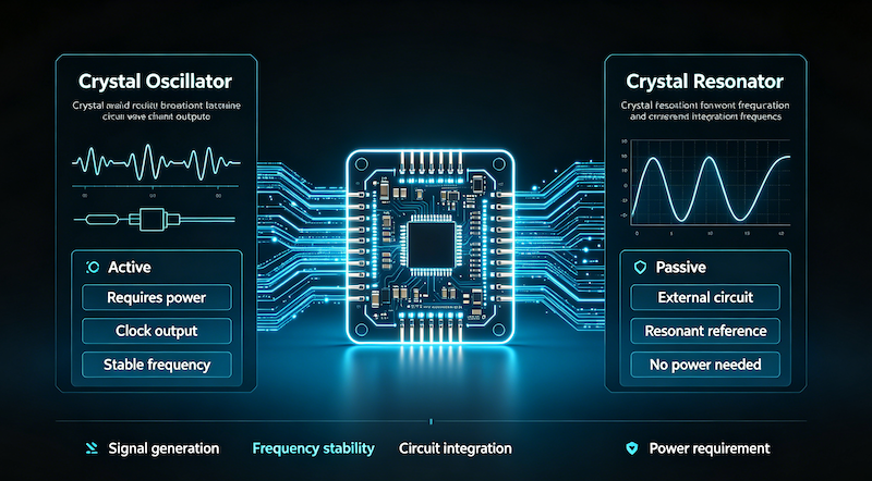
The terms are often used interchangeably, but they are fundamentally different components. One is a passive “raw material” that requires external circuitry to work. The other is a complete, self-contained module that outputs a stable clock signal the moment you apply power. Choosing the wrong one means either unnecessary cost or a design that fails to oscillate.
For engineers, procurement professionals, and PCB designers, understanding the difference between a crystal resonator and a crystal oscillator is not just technical knowledge—it is essential for getting the design right the first time.
This guide covers everything you need to know: internal structure, active vs passive operation, accuracy differences, cost considerations, applications, and how to choose the right timing component for your project.
Internal link: For a complete overview of timing components, see our Crystal Units and Oscillators product center.
What Is a Crystal Resonator?
A crystal resonator—often simply called a “crystal” or “XTAL”—is a passive component that uses the piezoelectric effect of quartz to provide a precise resonant frequency reference.
Internal structure:
- A thin slice of quartz crystal (the resonator element)
- Metal electrodes deposited on both sides of the crystal
- A metal or ceramic package with 2, 4, or more pins
- No active circuitry inside
How it works:
When an alternating voltage is applied across the crystal, the quartz mechanically vibrates at its natural resonant frequency. This frequency is determined by the physical dimensions and cut of the crystal. The crystal acts as a very high-Q (quality factor) resonant circuit.
Key characteristics:
- Passive device: Cannot generate a signal on its own
- Requires external circuitry: Needs an oscillator circuit (typically inside an MCU, SoC, or dedicated IC) plus external load capacitors to function
- Two pins typical: The most common package is a 2-pin cylinder (HC-49) or 4-pin SMD package
- Output: Provides a frequency reference, not a usable clock signal
- No voltage specification: Crystal resonators do not have a voltage rating—only frequency and load capacitance
Typical applications:
- MCU clock sources (most microcontrollers have built-in oscillator circuits)
- Low-cost, high-volume consumer electronics
- Designs where PCB space and cost are critical
External link: For a detailed technical introduction to quartz crystal resonators, see ScienceDirect’s Quartz Crystal Resonator overview.
Internal link: Browse our Crystal Units —available in HC-49 and SMD packages with frequencies from 32.768kHz to 100MHz.
What Is a Crystal Oscillator?
A crystal oscillator—often called an “XO” or “active crystal”—is a complete, self-contained timing module that outputs a stable clock signal directly.
Internal structure:
- A quartz crystal resonator (the frequency-determining element)
- An integrated oscillator circuit (amplifier and feedback network)
- Additional components for signal shaping and output drive
- A 4-pin or more package with power, ground, and output pins
- Optional: temperature compensation (TCXO), voltage control (VCXO), or oven control (OCXO) for enhanced stability
How it works:
The internal oscillator circuit provides the gain and feedback needed to sustain oscillation at the crystal’s resonant frequency. The active circuitry amplifies the crystal’s tiny signal and drives it to a usable logic-level output (typically a square wave). Apply power, and you get a stable clock signal—no external components required.
Key characteristics:
- Active device: Contains its own drive circuitry
- Standalone solution: No external components needed—just connect power and ground
- 4+ pins: Typically 4 pins (VDD, GND, output, and often a tri-state or enable pin)
- Output: Directly outputs a stable clock signal (typically square wave)
- Voltage specification: Requires a specific supply voltage (e.g., 3.3V or 5V)
Typical applications:
- FPGA, ASIC, and DSP clocks
- Communication equipment (5G, Wi-Fi modules)
- High-precision systems (GPS, servers, radar)
- Applications where design time and reliability are more important than component cost
External link: For the theory behind crystal oscillator circuits, refer to All About Circuits’ Crystal Oscillators tutorial.
Internal link: View our Crystal Oscillators —available in standard XO, TCXO, and VCXO variants.
Crystal Oscillator vs Crystal Resonator: Head-to-Head Comparison
| Feature | Crystal Resonator (XTAL) | Crystal Oscillator (XO) |
|---|---|---|
| Device Type | Passive | Active (contains IC) |
| Internal Circuitry | Quartz crystal only | Crystal + oscillator IC + amplifier |
| Power Required | No (passive) | Yes (VDD pin required) |
| External Components | Requires load capacitors + external oscillator circuit | None—just connect power |
| Pins | Typically 2 or 4 pins | Typically 4 or more pins |
| Output Signal | Frequency reference only (no direct output) | Stable clock signal (square wave) |
| Frequency Accuracy | ±0.005% to ±0.05% (quartz) | Similar to resonator, plus active compensation options |
| Frequency Stability | Good—depends on external circuit design | Excellent—internal compensation available |
| Cost | Lower | Higher (includes active circuitry) |
| Power Consumption | Lower (passive) | Higher (active circuitry) |
| Design Complexity | Higher—requires careful matching of load capacitance | Lower—plug-and-play |
| Typical Applications | MCU clock sources, low-cost designs | FPGA, communication, high-precision systems |
Inside the Crystal Resonator
The quartz crystal resonator is remarkably simple—and that simplicity is its strength.
At the heart of every crystal resonator is a precisely cut sliver of quartz. Quartz is a piezoelectric material: when mechanical pressure is applied, it generates a voltage; conversely, when a voltage is applied, it mechanically deforms. This piezoelectric effect is what makes quartz crystals such exceptional frequency references.
When an AC voltage is applied across the crystal, it physically vibrates at a specific frequency determined by its physical dimensions and cut. This mechanical resonance is extraordinarily stable—the crystal’s Q factor (a measure of frequency selectivity) is exceptionally high, making quartz crystals the most accurate and stable frequency references available for general-purpose electronics.
The catch: A crystal resonator cannot oscillate on its own. It needs to be placed inside an oscillator circuit—typically the one built into a microcontroller, SoC, or dedicated clock generator IC. The external circuit provides the gain and feedback to sustain oscillation. Load capacitors must be carefully matched to the crystal’s specified load capacitance; mismatched capacitors are a common cause of oscillation failure or frequency drift.
What this means for procurement: When buying crystal resonators, you need to specify:
- Frequency (e.g., 16.000MHz)
- Load capacitance (e.g., 12pF, 18pF, or 20pF)
- Package type (HC-49 through-hole, or SMD)
- Frequency tolerance (e.g., ±10ppm, ±20ppm, ±50ppm)
There is no voltage specification for a crystal resonator—it is a passive component.
Inside the Crystal Oscillator
The crystal oscillator takes the bare crystal and adds everything needed to turn it into a usable clock source.
Inside the package, you will find:
- A quartz crystal resonator (the frequency-determining element)
- An amplifier that provides the gain to sustain oscillation
- A feedback network that maintains stable oscillation
- Output buffer circuitry that drives a clean square wave signal
- Optional: temperature compensation circuitry (TCXO), voltage control (VCXO), or oven control (OCXO)
The active circuitry inside the chip creates a positive feedback loop—also known as negative resistance—that provides the stimulus for the crystal to start and maintain oscillation. Apply power to the VDD pin, and the oscillator outputs a stable clock signal within microseconds.
What this means for procurement: When buying crystal oscillators, you need to specify:
- Frequency (e.g., 50.000MHz)
- Supply voltage (e.g., 3.3V, 5V, or 1.8V)
- Output type (CMOS, LVDS, LVPECL, or sine wave)
- Frequency stability (e.g., ±25ppm, ±50ppm over temperature)
- Package type (typically 4-pin or more SMD)
The oscillator is a complete solution—no external load capacitors, no oscillator circuit design, no matching headaches.
Accuracy and Stability: The Real Difference
Both crystal resonators and crystal oscillators use the same quartz crystal technology at their core. The difference in accuracy comes down to two factors: external circuit design and temperature compensation.
Crystal resonator accuracy:
- Typical frequency tolerance: ±0.005% to ±0.05% (50ppm to 500ppm)
- Stability depends heavily on the external oscillator circuit design
- Load capacitor matching errors are a common source of frequency drift
- No built-in temperature compensation—frequency varies with temperature
Crystal oscillator accuracy:
- Similar base accuracy to a well-designed resonator circuit
- Internal circuitry maintains stable oscillation regardless of load
- TCXO variants can achieve ±0.5ppm to ±5ppm over temperature
- OCXO variants achieve ±0.001ppm or better
For most microcontroller applications, the difference is academic—both provide more than adequate accuracy. For communication systems, GPS, and high-speed data transmission, the oscillator’s integrated stability is a significant advantage.
External link: For precision timing applications, refer to the IEEE Xplore database for technical papers on oscillator design and phase noise.
Cost: The Trade-Off
The cost difference between a crystal resonator and a crystal oscillator is straightforward:
Crystal resonators are cheaper—often significantly so. The component itself costs less because it is a simpler passive device. However, the total cost of ownership must include:
- The external load capacitors
- PCB space for additional components
- Engineering time to design and debug the oscillator circuit
- Potential respin costs if the crystal fails to oscillate
Crystal oscillators cost more because they include active circuitry. But they also:
- Eliminate load capacitors and their PCB footprint
- Reduce engineering time (plug-and-play design)
- Lower the risk of oscillation failures
- Reduce board space requirements
The total cost equation: For high-volume production, the lower unit cost of crystal resonators often wins. For low-to-medium volume, the engineering time saved by using an oscillator can more than offset its higher unit cost.
Which One Should You Choose?
| Requirement | Recommended Component |
|---|---|
| Simple MCU design | Crystal resonator (most MCUs have built-in oscillator circuits) |
| Cost-sensitive high-volume production | Crystal resonator |
| FPGA, ASIC, or DSP clock | Crystal oscillator |
| Communication equipment (5G, Wi-Fi) | Crystal oscillator |
| High-precision or GPS timing | TCXO or OCXO oscillator |
| Fast design cycle | Crystal oscillator (plug-and-play) |
| Prototype or low-volume production | Crystal oscillator (reduces design risk) |
| Space-constrained design | Either—both are available in small SMD packages |
| Low-power design | Crystal resonator (lower power consumption) |
Decision Framework
Step 1: Check if your IC has a built-in oscillator circuit
- Most MCUs, SoCs, and processors have internal oscillator amplifiers → Crystal resonator is viable
- FPGAs and ASICs often require an external clock source → Crystal oscillator is preferred
Step 2: Evaluate your engineering resources
- Have you designed crystal oscillator circuits before? → Resonator is fine
- Is this your first crystal design? → Oscillator reduces risk
Step 3: Consider your production volume
- High volume (100k+ units) → Resonator’s lower unit cost wins
- Low to medium volume → Oscillator’s engineering savings may be more valuable
Step 4: Assess your accuracy requirements
- Standard MCU timing (±50ppm to ±100ppm acceptable) → Resonator works
- Communication, GPS, or high-speed data (±25ppm or better) → Oscillator (or TCXO) required
Step 5: Check PCB space
- Both are available in compact SMD packages
- Resonator requires additional load capacitors—more board space
- Oscillator includes everything in one package—less board space
Common Design Mistakes
Mistake 1: Buying a crystal resonator when you need an oscillator
Resonators require external circuitry. If your IC does not have a built-in oscillator circuit, a resonator will not work.
Solution: Check your IC datasheet before specifying the timing component.
Mistake 2: Forgetting the load capacitors for resonators
Crystal resonators require external load capacitors—typically 12pF to 20pF, matched to the crystal’s specified load capacitance. Omitting them is a common cause of oscillation failure.
Solution: Always include the load capacitors specified in the crystal datasheet.
Mistake 3: Specifying a resonator when you need a voltage specification
Crystal resonators do not have a voltage specification—they are passive components. Crystal oscillators require a specific supply voltage.
Solution: If your BOM includes a voltage parameter, you are specifying an oscillator, not a resonator.
Mistake 4: Underestimating the design effort for resonators
Getting a crystal resonator circuit to oscillate reliably requires careful PCB layout, correct load capacitance, and proper oscillator gain margin.
Solution: For complex or high-speed designs, consider using an oscillator to simplify the design.
Mistake 5: Confusing crystal oscillators with other oscillator types
Crystal oscillators (XO) are distinct from TCXO, VCXO, and OCXO variants. Each has different performance characteristics and costs.
Solution: Specify the exact oscillator type required for your application.
Frequently Asked Questions
What is the difference between a crystal resonator and a crystal oscillator?
A crystal resonator is a passive component that requires external circuitry to oscillate. A crystal oscillator is an active device with built-in oscillator circuitry that outputs a stable clock signal when powered.
Is a crystal oscillator better than a crystal resonator?
Neither is universally better. Oscillators offer plug-and-play convenience, better stability, and lower design risk but cost more. Resonators are cheaper and more flexible but require careful external circuit design.
Can a crystal resonator work without an IC?
No. A crystal resonator requires an external oscillator circuit—typically the one built into a microcontroller or SoC—to generate a clock signal.
How do I know if I need a crystal resonator or oscillator?
Check your IC datasheet. If it has built-in oscillator pins (XTAL1/XTAL2), you can use a resonator. If it requires an external clock input, you need an oscillator.
What is the typical accuracy of a crystal resonator?
Quartz crystal resonators typically offer ±0.005% to ±0.05% (±50ppm to ±500ppm) frequency tolerance.
What is the typical accuracy of a crystal oscillator?
Crystal oscillators offer similar base accuracy with options for temperature compensation. TCXO variants achieve ±0.5ppm to ±5ppm over temperature.
Why do crystal oscillators have 4 pins?
The 4 pins are typically VDD (power), GND (ground), output (clock signal), and an enable/tri-state pin. Some variants may have additional pins for voltage control or temperature compensation.
What is the difference between a crystal oscillator and a TCXO?
A TCXO (Temperature-Compensated Crystal Oscillator) includes circuitry that compensates for frequency drift caused by temperature changes, providing much higher stability over temperature.
Do you offer both crystal resonators and crystal oscillators?
Yes. Vistar Electronics supplies a full range of crystal units (resonators) and crystal oscillators (XO, TCXO, VCXO, OCXO) for PCB applications. Contact our engineering team for specific frequency and package requirements.
Timing Components from Vistar Electronics
At Vistar Electronics, we understand the nuances of timing component selection. Our crystal and oscillator portfolio includes:
Crystal Units (Resonators):
- HC-49 through-hole and SMD packages
- Frequencies from 32.768kHz to 100MHz
- Load capacitance: 8pF to 30pF
- Frequency tolerance: ±10ppm to ±50ppm
Crystal Oscillators (XO):
- Standard XO, TCXO, VCXO, and OCXO variants
- 4-pin and more SMD packages
- Supply voltages: 1.8V, 2.5V, 3.3V, 5.0V
- Output options: CMOS, LVDS, LVPECL
- Frequency stability: ±10ppm to ±50ppm (standard), ±0.5ppm to ±5ppm (TCXO)
Whether you are designing a simple microcontroller board, a high-speed communication system, or a precision GPS receiver, the right timing component starts with understanding the difference between a crystal resonator and a crystal oscillator. We can help you specify it, source it, and integrate it.
Internal link: Browse our full range of Crystals and Oscillators .
For technical specifications, samples, or application support, contact the Vistar Electronics engineering team.


