

2.54mm Triple Row Pin Header | Right Angle Through-Hole Male Header
2.54mm Triple Row Pin Header — Product Overview (Three Row Pin Header for High-Density Interconnects)
The PH-2.54-3R-DIP is a three row pin header featuring a standard 2.54mm (0.100″) pitch and right-angle through-hole mounting. This high-density connector provides up to 120 contact positions in a compact footprint, enabling engineers to route multiple signals, power, and ground connections in space-constrained PCB layouts. Whether you’re designing a programmable logic controller (PLC), an embedded computer, or a communication module, this connector delivers the mechanical robustness and electrical performance required for demanding industrial environments.
Manufactured with precision-stamped brass contacts (phosphor bronze optional) and available with gold or tin plating, the 2.54mm triple row pin header ensures low contact resistance (≤20 mΩ) and stable signal integrity across a wide temperature range (-40°C to +105°C). The high-temperature PA6T insulator meets UL94V-0 flammability standards, making it suitable for wave soldering and reflow processes.
Right Angle Pin Header — Full Technical Specifications
| Parameter | Value | Notes |
|---|---|---|
| Part Number | PH-2.54-3R-DIP | Standard catalog item |
| Pitch | 2.54 mm (0.100″) | Industry standard |
| Rows | Triple Row (3 Rows) | High-density configuration |
| Positions | 9–120 Pin (3×N) | Customizable |
| Mounting Type | Through-Hole DIP | Wave or hand soldering |
| Orientation | Right Angle (90°) | Side-exit PCB mount |
| Contact Material | Brass / Phosphor Bronze | Precision stamped |
| Contact Plating | Gold or Tin | Optional |
| Current Rating | 3A Max | Per contact |
| Voltage Rating | 250V AC | — |
| Contact Resistance | ≤ 20 mΩ | Initial |
| Insulation Resistance | ≥ 1,000 MΩ | At 500V DC |
| Dielectric Strength | 500V AC for 1 minute | No breakdown |
| Operating Temperature | −40 °C to +105 °C | Industrial grade |
| Storage Temperature | −40 °C to +105 °C | — |
| Insulator Material | PA6T, UL94V-0 | High-temperature thermoplastic |
| Compliance | RoHS 3, REACH | Global export ready |
| Packaging | Bag / Tray | Production ready |
Why Engineers Choose This Through-Hole Male Header for Robust PCB Anchoring
Through-Hole DIP — Maximum Pull-Out & Side-Load Resistance
Through-hole pins pass through the PCB and are soldered on both sides, creating a mechanically robust dual-anchored joint that withstands high vibration and cable tension — ideal for industrial and automotive applications.
Standard 2.54mm Pitch — Universal Compatibility
Industry-standard 0.100″ spacing ensures compatibility with a wide range of female headers, IDC connectors, and PCB footprints, simplifying design reuse and component sourcing.
Triple Row High-Density Layout
Three rows of contacts deliver up to 120 connection points in a single compact footprint, maximizing PCB utilization and reducing board space requirements in high-density applications.
Right Angle Space-Saving Design
The 90° orientation mounts the connector parallel to the PCB surface, enabling edge-board connections that minimize vertical height — ideal for 1U rackmount equipment and compact enclosures.
Gold or Tin Plating Available
Choose gold plating for enhanced corrosion resistance and low contact resistance in harsh or high-reliability applications, or tin plating for cost-effective general-purpose use.
OEM Customization — Pin Count & Pin Length
Vistar offers flexible customization including pin counts from 9 to 120 (3×N), custom pin lengths, and special plating requirements. Free engineering samples available.
Where to Use This PCB Pin Header — Applications for Industrial, Embedded & Communication Systems
As a versatile PCB pin header, the PH-2.54-3R-DIP is found across a wide range of industries where high-density board-to-board interconnection is required. Its 2.54mm pitch, right-angle through-hole design, and customizable pin configurations make it a preferred choice for engineers designing industrial, embedded, and communication systems.
2.54mm Triple Row Pin Header — Frequently Asked Questions
What is the difference between the PH-2.54-3R-DIP right-angle and a straight pin header?
The PH-2.54-3R-DIP right-angle connector mounts parallel to the PCB surface, enabling edge-board connections that minimize vertical height — ideal for 1U rackmount equipment and compact enclosures. A straight pin header mounts perpendicular to the PCB, providing vertical connections suitable for stacked board architectures and through-hole PCB mounting.
What is the MOQ and can I get a free sample?
Standard MOQ is 1,000 pieces with a 2–4 week production lead time. Free samples are available for qualified engineering and product development projects. Contact sales@vistarelectronics.com with your company details, project application, and part number (PH-2.54-3R-DIP), or click the “Get a Quote” button at the top of this page.
Can this pin header be customized for pin count and plating?
Yes. Vistar offers OEM/ODM customization including pin counts from 9 to 120 (3×N), custom pin lengths, plating options (gold or tin), and special packaging requirements. Contact our engineering team to discuss your specific needs.
Is the PH-2.54-3R-DIP RoHS and REACH compliant?
What is the recommended PCB footprint for this connector?
Recommended PCB footprint: plated through-hole diameter 1.0 mm, pad diameter 1.6 mm, pin spacing 2.54 mm, row spacing 2.54 mm. For complete mechanical drawings and 3D STEP models, contact Vistar Electronics for design files.
Can this header mate with standard female headers?
Yes. This 2.54mm pin header is fully compatible with standard 2.54mm female headers, IDC connectors, and PCB socket connectors. The through-hole design ensures reliable mechanical and electrical mating with industry-standard counterparts.
Understanding the 2.54mm Triple Row Pin Header — A Complete Guide for Engineers and Procurement Professionals
What Is a 2.54mm Triple Row Pin Header?
A 2.54mm triple row pin header is a board-to-board connector featuring three parallel rows of male pins with a standard 0.100″ (2.54mm) pitch. This configuration provides high-density interconnection in a compact footprint, making it ideal for applications requiring multiple connections in limited PCB space. The PH-2.54-3R-DIP is a right-angle through-hole version of this connector, designed to mount parallel to the PCB surface for space-efficient edge-board connections.
The triple row design offers significant advantages over single or dual-row alternatives. With up to 120 positions available (3×N configuration), it provides up to 50% more connection points than dual-row headers in the same PCB footprint. This makes it particularly valuable in industrial controllers, embedded systems, and communication equipment where board space is at a premium and multiple signals, power, and ground connections are required.
Triple Row vs Dual Row Pin Header — How to Choose
When selecting between a three row pin header and dual-row alternatives, consider the following factors. Single-row headers offer the simplest routing but the lowest density. Dual-row headers provide twice the connection points in a similar footprint, suitable for moderate-density applications. Triple-row headers offer the highest density, with up to 50% more connections than dual-row in the same PCB footprint, making them ideal for high-density applications where board space is at a premium.
For programming headers (JTAG, SWD, ISP), follow the reference pinout defined by the microcontroller vendor to maintain cable compatibility. For general-purpose board-to-board interconnection, the triple row configuration provides the most flexibility for routing multiple signals, power rails, and ground connections in a limited space.
Why Choose 2.54mm Pitch?
The 2.54mm (0.100″) pitch is the industry-standard spacing for pin header connectors, originating from the legacy of dual in-line package (DIP) integrated circuits. This standard pitch offers several benefits: universal compatibility with a wide range of female headers, IDC connectors, and PCB footprints; simplified PCB layout with standard grid spacing; and easy integration with existing designs and manufacturing processes.
For engineers developing new products, the 2.54mm pitch ensures broad component availability, competitive pricing, and interoperability with a wide range of mating connectors. For legacy systems, it guarantees backward compatibility with existing PCB designs and tooling.
Right Angle vs Straight Pin Headers
Choosing between right angle pin header and straight pin headers depends on your PCB layout and mechanical constraints. Right-angle pin headers mount parallel to the PCB surface, enabling edge-board connections that minimize vertical height — ideal for 1U rackmount equipment, compact enclosures, and applications where vertical clearance is limited. Straight pin headers mount perpendicular to the PCB, providing vertical connections suitable for stacked board architectures and through-hole PCB mounting.
The PH-2.54-3R-DIP features a right-angle orientation, making it particularly well-suited for edge-mount applications where connectors need to be accessed from the side of the PCB. This design is commonly used in industrial controllers, communication equipment, and test instruments where front-panel or side-panel access is required.
Through-Hole Advantages for Industrial Applications
The through-hole DIP mounting of this through-hole male header provides several advantages over SMD alternatives. First, the through-hole pins pass through the PCB and are soldered on the opposite side, creating a mechanically robust joint that can withstand significant mechanical stress and vibration. Second, the through-hole design is compatible with wave soldering processes, making it suitable for high-volume manufacturing. Third, the through-hole pins provide excellent pull-out resistance, reducing the risk of connector detachment in high-vibration industrial environments.
For industrial applications such as PLCs, industrial computers, and automation equipment, the through-hole design is often the preferred choice for reliable board-to-board interconnection.
Applications in Industrial Electronics
PCB pin header connectors are widely used across industrial electronics, including programmable logic controllers (PLCs), industrial PCs, embedded controllers, and automation equipment. In these applications, the high-density triple-row configuration provides reliable interconnection for multiple I/O modules, power supplies, and communication interfaces. The through-hole mounting ensures robust mechanical anchoring in high-vibration industrial environments, while the 2.54mm pitch guarantees compatibility with standard PCB layouts and manufacturing processes.
Beyond industrial applications, triple row pin headers are also found in medical electronics, communication equipment, test and measurement instruments, and consumer electronics where high-density board-to-board interconnection is required.
OEM Customization and Free Samples
Vistar Electronics offers comprehensive OEM/ODM customization for the PH-2.54-3R-DIP triple row pin header. Customization options include pin counts from 9 to 120 positions (3×N configuration), custom pin lengths, plating options (gold or tin), and special packaging requirements. Our engineering team works closely with you to tailor the connector to your exact specifications.
Free engineering samples are available for qualified projects. Contact us at sales@vistarelectronics.com with your company details and project description to request samples or discuss your custom requirements.
Why Choose Vistar as Your Pin Header Manufacturer
Vistar Electronics is a trusted pin header manufacturer and supplier serving customers in industrial automation, embedded systems, communication equipment, and consumer electronics for over a decade. Our 2.54mm pin header lineup covers single, dual, and triple-row configurations with mounting options including through-hole DIP, SMT, right-angle, and straight orientations.
We offer competitive pricing, flexible MOQs, and responsive customer support to ensure your project stays on track. With ISO 9001:2015 certification and a commitment to continuous improvement, Vistar is your reliable partner for high-quality interconnect solutions. Whether you need standard catalog items or custom OEM configurations, our engineering team is ready to assist you from prototype to production.
For more technical resources, including PCB layout guidelines, pin header selection guides, and application notes, visit our technical blog or contact our engineering support team directly.
PH-2.54-3R-DIP — 2.54mm Triple Row Pin Header | Right Angle Through-Hole Male Header | RoHS 3 & REACH Compliant | OEM/ODM Available

2.54mm Pin Header SMT Double Row (PHC-254) | Dual Plastic PCB Board-to-Board Connector

2.0MM straight pin header

2.54mm Pin Header Double Plastic SMT – SMT Male Header for PCB Interconnection

2.0mm U Type Pin Header – Through-Hole Male Header Connector for Reliable PCB Board-to-Board Connections

2.0MM pin header three-row

1.27MM pin header double row 90°

1.27mm Vertical SMT Pin Header 1.0A | Male Header Brass Contact PA6T UL94V-0 Black PCB Connector

2.54mm Pin Header Dual Row SMT Connector for High-Reliability PCB Applications

40 Pin 2.54mm Pin Header: Complete Selection & Specification Guide
A contract manufacturer once showed me a batch of 500 industrial I/O boards that failed final test. The symptom was intermittent analog...

Market Trends and Prospects for Pin Header Connector in china Industry (2025-2030)
The industry of pin header connector in China is poised for steady growth from 2025 to 2030, driven by technological advancements and...
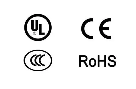
The Main international standards and certifications in the pin header industry 2025
International standards and certifications in the pin header industry are crucial for ensuring the quality, safety, and compatibility of connector products. The...