

1.27mm Pin Header Double Row 90° for Compact PCB Connections
1.27mm Pin Header Double Row Right Angle for Space-Saving PCB Designs
When PCB space is limited, connector selection becomes a balance between contact density, mechanical layout, assembly requirements, and long-term reliability. The 1.27mm right angle pin header configuration is designed for applications that need more contacts in a compact footprint while keeping the mating direction parallel to the PCB.
This right-angle male header uses a 1.27mm pitch and dual-row arrangement to provide a higher connection density than many conventional 2.54mm headers. The 90-degree orientation is particularly useful when vertical clearance is restricted or when a connector must route signals toward the edge of a PCB, daughterboard, module, or enclosure.
For engineers and purchasing teams, the important considerations are not only pitch and row configuration. Contact material, insulator performance, current rating, mating orientation, PCB layout, packaging, and compatibility with the mating connector should all be evaluated before production.
1.27mm Right Angle Pin Header — When to Use It
A 1.27mm right angle pin header changes the direction of the mating interface by 90 degrees, allowing the connected board, cable, or mating socket to extend horizontally rather than vertically from the PCB. This geometry can make a significant difference in compact electronic equipment where enclosure height is limited.
The 1.27mm pitch provides a smaller contact spacing than the widely used 2.54mm pitch. This allows designers to place more contacts within a similar board length or reduce the overall connector footprint when the number of required circuits is fixed.
The right-angle structure is also useful for PCB edge connections. Instead of routing a mating connector upward from the board, the connector can direct the mating interface toward the side of the assembly. This can simplify enclosure design and provide additional freedom when positioning displays, communication modules, control boards, or other daughterboards.
When selecting a compact header, engineers should check the complete mechanical drawing rather than relying only on the nominal pitch. Important dimensions include pin length, insulator height, row-to-row spacing, terminal extension, PCB hole diameter, and the available mating clearance.
1.27mm Dual Row Pin Header for Higher Contact Density
A 1.27mm dual row pin header combines two parallel rows of contacts in a compact connector body. Compared with a single-row design, the dual-row arrangement provides more electrical positions without requiring a proportional increase in connector length.
This configuration can be particularly useful when a PCB needs to carry multiple signals, power connections, grounds, control lines, or communication interfaces through a single mating location. Instead of spreading contacts across several individual connectors, engineers can consolidate the interface into a higher-density connector arrangement.
The dual-row structure can also simplify PCB routing when the electrical interface has a large number of circuits. However, designers should consider escape routing, trace width, ground allocation, and signal integrity requirements during the PCB layout stage.
For production designs, the mating connector must also be checked carefully. Pitch alone does not guarantee compatibility. The number of positions, contact geometry, insulator dimensions, mating height, and terminal orientation all need to match the corresponding female header or socket.
Right Angle PCB Pin Header — Construction and Specifications
A right angle PCB pin header is normally built around three fundamental elements: conductive contacts, an insulating housing, and a mounting interface designed to establish a stable PCB connection.
| Parameter | Specification | Notes |
|---|---|---|
| Pitch | 1.27mm | Compact spacing |
| Part Number | PH-1.27-90 | |
| Configuration | Double Row | Higher density |
| Contact Orientation | 90° Right Angle | Parallel to PCB |
| Connector Type | Male Pin Header | — |
| Current Rating | 1.5A | Per contact |
| Contact Material | Brass | Conductive |
| Insulator Material | PA6T, UL94V-0 | Black, high-temperature |
| Packaging | Bag / Tray | Production ready |
| Compliance | RoHS, REACH | Global export ready |
The 1.5A current rating provides a useful reference for circuit planning, but engineers should always evaluate actual current requirements according to operating temperature, PCB construction, contact configuration, duty cycle, and the complete electrical specification of the final assembly.
Brass is commonly used for connector contacts because it provides a practical balance of conductivity, mechanical strength, formability, and manufacturing cost. The insulating housing separates adjacent contacts and provides the dimensional structure required for consistent mating.
The use of PA6T with a UL94V-0 flame-retardant rating is appropriate for electronic assemblies where the connector housing must maintain dimensional stability and meet defined flammability requirements. For a production project, the applicable material documentation should be confirmed against the customer’s compliance requirements.
1.27mm Board to Board Connector for Compact Electronic Assemblies
A 1.27mm board to board connector can provide a compact interface between a main PCB and a secondary board, module, control board, or daughtercard. The 90-degree configuration is especially useful when the two boards need to be positioned at an angle or when the available enclosure space favors a horizontal mating direction.
Board-to-board interconnection is common in industrial electronics, embedded computing, communication equipment, measurement instruments, control systems, and compact consumer devices. Instead of using wires and cable assemblies for every internal connection, a pin header and compatible socket can provide a repeatable separable interface.
Mechanical alignment is important in these applications. The connector position should be coordinated with the PCB mounting holes, enclosure tolerances, mating connector, and board thickness. Even a small dimensional mismatch can create unnecessary insertion force or place mechanical stress on solder joints.
For applications involving frequent service or module replacement, engineers should also evaluate the expected mating cycle requirements and select an appropriate contact finish. For less frequently serviced products, cost and availability may have a greater influence on the final selection.
1.27mm Pin Header Double Row 90° — Key Features
1.27mm Compact Pitch
Supports compact PCB layouts and higher contact density compared to conventional 2.54mm headers.
Dual-Row Construction
Provides more contacts within a limited connector footprint while maintaining a compact overall size.
90-Degree Right Angle
Directs the mating interface parallel to the PCB, reducing vertical clearance requirements.
1.5A Current Rating
Suitable for many signal and moderate-power interconnection requirements when applied within specified conditions.
Brass Contacts
Provide a practical balance of conductivity, mechanical strength, and formability.
PA6T UL94V-0 Housing
High-temperature insulator material designed for demanding electronic assembly environments.
Where to Use This Right Angle PCB Pin Header — Applications Across Industries
As a versatile 1.27mm board to board connector, this right-angle dual-row header is found across a wide range of applications where compact PCB interconnection and space-efficient design are required.
Right Angle vs Straight Pin Headers — Which One to Choose?
When selecting a pin header for your PCB, understanding the differences between right-angle and straight configurations is essential.
| Feature | Right Angle (90°) | Straight |
|---|---|---|
| Mating Direction | Parallel to PCB | Perpendicular to PCB |
| Vertical Clearance | Lower | Higher |
| Typical Use | PCB edges, compact enclosures, horizontal modules | Board stacking, vertical modules |
| Layout Flexibility | Useful for horizontal routing | Useful for vertical board connections |
| Space Consideration | Optimizes vertical space | Optimizes some horizontal layouts |
The correct choice depends on the physical architecture of the product. If the enclosure has limited height, a right-angle configuration may provide a better mechanical solution. If boards are stacked vertically, a straight configuration may be more appropriate.
PCB Layout Considerations for 1.27mm Dual Row Pin Header
Before placing the connector footprint, engineers should verify the manufacturer’s mechanical drawing and recommended PCB pattern. The footprint should account for the complete terminal geometry rather than only the nominal pitch.
Footprint Design
- Pin Spacing: 1.27mm between pins in each row
- Row Spacing: Verify from the mechanical drawing
- Plated Through-Hole Diameter: Sized for the terminal geometry
- Pad Diameter: Follow the manufacturer’s recommendation
Routing Considerations
- For dual-row connectors, routing density is an important consideration.
- Ground pins can be strategically allocated between sensitive signals where appropriate.
- Power circuits should be reviewed for current distribution and thermal conditions.
Mechanical Support
- If the connector is positioned close to a PCB edge, evaluate board thickness, mounting structure, and mating force.
- In applications with repeated insertion and extraction, mechanical stress can eventually affect solder joints or PCB pads.
- For production designs, engineers should validate the footprint with physical samples before releasing the PCB for mass production.
How to Select the Right Header for Your PCB
Choosing a connector should begin with the mechanical and electrical requirements of the application.
1. Pitch
Confirm that the selected pitch matches the mating component and the available PCB space. The 1.27mm pitch is ideal for compact designs.
2. Row Configuration
Determine the number of rows. A dual-row configuration is useful when a higher contact count is needed without significantly increasing connector length.
3. Orientation
Straight headers are generally used for vertical mating, while right-angle headers are suitable when the mating direction needs to run parallel to the PCB.
4. Electrical Requirements
Confirm the current rating, voltage rating, contact resistance, insulation requirements, and any environmental requirements that apply to the finished product.
5. Mechanical Compatibility
Check PCB hole dimensions, terminal length, insulator dimensions, mating height, connector alignment, and clearance around nearby components.
Need a different configuration? Explore our full pin header connector range.
1.27mm Pin Header Double Row 90° — Frequently Asked Questions
What is a 1.27mm pin header used for?
A 1.27mm pin header is commonly used in compact PCB assemblies where designers need higher contact density than a traditional 2.54mm header can provide. Typical applications include embedded systems, communication modules, industrial electronics, instrumentation, and compact board-to-board connections.
What does double row mean?
Double row means that the connector contains two parallel rows of electrical contacts. This configuration increases the number of available contacts within a compact connector footprint and can simplify high-density PCB interconnection.
Why use a 90-degree pin header?
A 90-degree or right-angle header changes the mating direction so that the mating connector extends parallel to the PCB. This can help reduce vertical clearance requirements and is useful for PCB-edge and compact enclosure applications.
Is this connector suitable for board-to-board applications?
Yes. The compact pitch and right-angle configuration can be considered for board-to-board applications where the mating geometry, position count, PCB spacing, and electrical specifications match the requirements of the mating connector.
What is the current rating?
The listed current rating is 1.5A. Actual operating conditions should be evaluated against temperature, contact configuration, PCB design, and the electrical requirements of the finished application.
What material is used for the contact?
The listed contact material is brass. Contact plating and other material details should be confirmed from the current product specification when they are critical to the application.
What is the insulator material?
The current specification lists PA6T with a UL94V-0 black insulating housing. Customers with specific material or compliance requirements should request the applicable documentation before production approval.
Can the connector be customized?
Custom requirements can be discussed for different pin counts, dimensions, orientations, plating options, and other mechanical or electrical parameters. For OEM or ODM projects, providing a drawing or target specification will help the engineering team evaluate feasibility.
What is the MOQ and can I get a free sample?
Standard MOQ is 1,000 pieces with a 2–4 week production lead time. Free samples are available for qualified engineering and product development projects. Contact sales@vistarelectronics.com with your company details, project description, and requirements.
1.27mm Pin Header Double Row 90° — Complete Guide for Engineers and Procurement Professionals
Why Choose a 1.27mm Pitch for PCB Interconnection?
Connector pitch directly influences the amount of PCB space required for an electrical interface. A 1.27mm pitch is half the nominal spacing of a 2.54mm header, making it attractive for designs that require more contacts within a restricted area.
This does not mean that a smaller pitch is automatically better. A compact pitch can make PCB routing more demanding, especially when many high-speed or sensitive signals are concentrated in a small area. Engineers should therefore select pitch based on the complete system architecture rather than simply choosing the smallest available connector.
The 1.27mm format is a practical middle ground for many compact electronic products. It offers greater density than traditional 2.54mm headers while remaining more manageable for PCB assembly and mechanical design than some ultra-fine-pitch interconnect technologies.
Right Angle vs Straight — Making the Right Choice
When selecting a pin header for your PCB, the choice between right-angle and straight configurations depends on your mechanical constraints. Right-angle headers direct the mating interface parallel to the PCB, making them ideal for edge-mount applications and compact enclosures where vertical clearance is limited. Straight headers direct the mating interface perpendicular to the PCB, making them suitable for board stacking and vertical module connections.
Applications Across Industries
This 1.27mm dual row pin header is widely used across multiple industries. Embedded control systems use it for processor board and expansion module connections. Industrial electronics rely on it for compact internal connections between controller and interface boards. Communication equipment uses it for board-level connections inside routers and gateways. Instrumentation uses it for display, control, and sensor board connections. Consumer electronics and IoT equipment use it for compact board-to-board interfaces.
Manufacturing and Quality Considerations
For OEM and contract manufacturing projects, connector quality should be evaluated across materials, dimensions, plating, electrical performance, mechanical retention, and production consistency. Material consistency is important because contact geometry directly influences mating performance. Insulator dimensional stability is also important for maintaining alignment between the two rows of contacts.
For higher-volume production, packaging should be matched to the customer’s assembly process. Bag and tray packaging can be suitable for manual handling, kitting, sampling, and selected automated production workflows. For large-scale automated assembly, customers should confirm the available packaging options before placing a production order.
Why Choose Vistar as Your Pin Header Connector Supplier
Vistar Electronics is a trusted pin header connector manufacturer serving customers in consumer electronics, industrial automation, medical devices, and communication equipment. Our pin header lineup covers 1.27mm, 2.0mm, and 2.54mm pitches with single, dual, and triple-row configurations and SMT, DIP, right-angle, and vertical mounting options.
With ISO 9001:2015 certification and a commitment to continuous improvement, Vistar is your reliable partner for high-quality interconnect solutions. For more technical resources, including PCB layout guidelines and connector selection guides, visit our technical blog or contact our engineering support team directly.
Explore our full range of pin header connectors and related content:
Technical Reference and Industry Standards
Connector selection should always be validated against the applicable component specification, PCB design requirements, and assembly process. For broader connector and PCB manufacturing guidance, engineers can consult recognized industry resources such as the IPC standards organization and UL safety and compliance resources.
For material and connector technology references, the TE Connectivity engineering resource also provides useful information about connector technologies, contact systems, and interconnection design.
Need Custom Pin Header Connector Solutions?
Vistar Electronics manufactures pin header connectors in 1.27mm, 2.0mm, and 2.54mm pitches with single, dual, and triple-row configurations and SMT, DIP, right-angle, and vertical mounting options. Custom pin counts, plating, and packaging available for OEM projects.
1.27mm Pin Header Double Row 90° — Right Angle PCB Pin Header | 1.5A | RoHS & REACH Compliant | OEM/ODM Available

1.27mm Vertical SMT Pin Header 1.0A | Male Header Brass Contact PA6T UL94V-0 Black PCB Connector

2.0mm U Type Pin Header – Through-Hole Male Header Connector for Reliable PCB Board-to-Board Connections

2.54mm Pin Header Dual Row SMT Connector for High-Reliability PCB Applications

2.54mm Triple Row Pin Header | Right Angle Through-Hole Male Header

2.0MM straight pin header

2.0MM pin header three-row

2.54mm Pin Header Double Plastic SMT – SMT Male Header for PCB Interconnection

2.54mm Pin Header SMT Double Row (PHC-254) | Dual Plastic PCB Board-to-Board Connector

40 Pin 2.54mm Pin Header: Complete Selection & Specification Guide
A contract manufacturer once showed me a batch of 500 industrial I/O boards that failed final test. The symptom was intermittent analog...

Market Trends and Prospects for Pin Header Connector in china Industry (2025-2030)
The industry of pin header connector in China is poised for steady growth from 2025 to 2030, driven by technological advancements and...
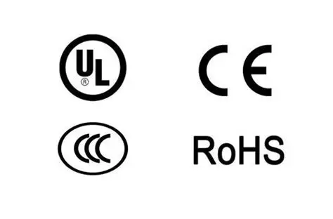
The Main international standards and certifications in the pin header industry 2025
International standards and certifications in the pin header industry are crucial for ensuring the quality, safety, and compatibility of connector products. The...