Vistar Electronics manufactures precision pin header connectors in 0.8mm, 1.0mm, 1.27mm, 2.0mm and 2.54mm pitch. Available in single row, dual row, straight, right angle, SMT & through‑hole. Request free samples and download 3D STEP files instantly.
| Pitch | Rows | Orientation | Mounting | Plating | Current Rating | Insulator Material |
|---|---|---|---|---|---|---|
| 0.8 mm | Single / Dual | Straight | SMT | Gold Flash | 0.5 A | LCP, UL 94V‑0 |
| 1.0 mm | Single / Dual | Straight / Right Angle | SMT / DIP | Gold / Tin | 1.0 A | PA6T, UL 94V‑0 |
| 1.27 mm | Single / Dual | Straight / Right Angle | SMT / DIP | Gold / Tin | 1.5 A | PA6T, UL 94V‑0 |
| 2.0 mm | Single / Dual | Straight / Right Angle | SMT / DIP | Gold / Tin | 2.0 A | PA6T, UL 94V‑0 |
| 2.54 mm | Single / Dual / Triple | Straight / Right Angle | SMT / DIP | Gold / Tin | 3.0 A | PBT, UL 94V‑0 |


From ultra‑fine 0.8mm to industry‑standard 2.54mm, our pin header connectors cover every compact to prototyping need.
Choose single row pin headers for simple signal routing, or dual/triple row for higher density — all with the same proven square post design.
Vertical straight pin headers and right angle pin headers for horizontal board mating — optimize your PCB layout and enclosure space.
Surface‑mount pin header connectors for automated assembly, through‑hole for robust mechanical anchoring — both available with tape‑reel or tray packaging.
Gold‑plated contacts for superior conductivity and corrosion resistance; tin‑plated for cost‑sensitive applications. All pin headers meet RoHS 3 and REACH.
Produced under ISO 9001, fully compliant with RoHS 3, REACH SVHC, and UL 94V‑0. Full material declarations and life‑test reports available.
Over 100 million pin header connectors shipped annually from our ISO 9001 facility. Trusted by industrial, automotive, and consumer electronics OEMs worldwide.
Validate fit and performance with free pin header samples. Download 2D drawings, 3D STEP files, and PCB footprints in Altium, Eagle, and KiCad formats instantly.
Need a specific pin length, stacking height, or right‑angle orientation? Our OEM/ODM service delivers custom pin headers in as fast as 5 days.
Watch pin header soldering and assembly videos, or book a video call with our engineers for footprint review and application guidance.
Standard 2.54mm pin headers for prototyping shields, sensors, and microcontroller boards — the universal interconnect for makers and developers.
High‑reliability pin header connectors in 2.0mm and 2.54mm pitch for PLCs, motor drives, and ruggedized data loggers.
Gold‑plated fine‑pitch pin headers ensure low contact resistance in patient monitors, portable ultrasound, and diagnostic instruments.
1.0mm and 1.27mm SMT pin headers for smartphones, tablets, and wearables where board space is at a premium.
High‑temp pin header connectors rated -40°C to +105°C for dashboard clusters, infotainment, and ADAS modules.
Right‑angle and dual‑row pin headers for wireless modules, gateways, and networking equipment requiring reliable board‑to‑board connections.
A pin header connector is one of the most fundamental components in electronics — a male connector made of one or more rows of metal pins staked into a plastic insulator. It mates with a female socket (often called a female header or receptacle) to create a reliable board‑to‑board or wire‑to‑board connection. The term pin header is often used interchangeably with “male header,” “PCB header,” or simply “header.” The pins are typically square posts (0.64mm or 0.5mm square) made of brass or phosphor bronze, and can be straight or bent at a right angle. The insulator is usually a high‑temperature thermoplastic like PBT, PA6T, or LCP, rated UL 94V‑0. For a broader history of connector technology, see Wikipedia’s entry on pin headers.
Because of their simplicity and low cost, pin header connectors are found in virtually every electronic device: Arduino shields, computer motherboards, industrial control boards, medical instruments, and automotive modules. They provide a separable interface that allows designers to easily swap modules, upload firmware, or connect off‑board peripherals. The most recognizable variant is the 2.54mm (0.1 inch) pitch single‑row header, but the family spans pitches from 0.8mm up to 5.08mm and configurations from 2 to 80 positions per row.
The pin header connector family is extensive, but all variants can be classified by a handful of characteristics: number of rows, pin orientation, mounting style, and pitch. Understanding these types is the first step toward specifying the exact part you need.
A single row pin header has one line of pins. It is the simplest, most cost‑effective form, and is used whenever you only need a few signals or when board real estate is tight. Typical positions range from 1 to 40 pins, though custom lengths are easily produced.
A dual row pin header packs two parallel rows of pins into the same length, doubling the connection density. Common in memory modules, display interfaces, and industrial backplanes. We stock dual‑row headers in all standard pitches, with or without shrouds.
A straight pin header has pins that exit perpendicular to the PCB, allowing a mating connector to be plugged in vertically. This is the default orientation for most board‑to‑board stacking applications.
A right angle pin header has pins bent 90 degrees so the mating direction is parallel to the board surface. This saves vertical clearance and is ideal for edge‑mounted connectors, front panels, and low‑profile enclosures.
Surface‑mount pin header connectors have gull‑wing or J‑lead terminals that sit on PCB pads and are reflow‑soldered. They enable fully automated assembly, double‑sided board population, and compact layouts. Available in tape‑and‑reel packaging for high‑volume pick‑and‑place.
Through‑hole pin headers have pins that pass through the PCB and are soldered on the opposite side. They provide superior mechanical anchoring and are preferred for connectors that will be mated and unmated frequently, or in high‑vibration environments.
Pin header connector pitch — the distance from one pin center to the next — is the single most important dimensional parameter. The table below summarizes the five most common pitches and where they are used.
| Pitch | Typical Applications | Pin Size (Square) | Mating Cycles |
|---|---|---|---|
| 0.8 mm | Wearables, micro‑displays, compact medical sensors | 0.3 mm | 30 |
| 1.0 mm | Smartphones, tablets, miniaturized IoT modules | 0.4 mm | 50 |
| 1.27 mm | Compact embedded systems, laptop docking, communication boards | 0.5 mm | 100 |
| 2.0 mm | Industrial control, automation, power supplies | 0.5 mm | 200 |
| 2.54 mm | Arduino, Raspberry Pi, breadboarding, universal PCB interconnect | 0.64 mm | 500+ |
When selecting pitch, consider not only the available board space but also the current‑carrying capacity and the robustness required.
One of the most common questions from engineers new to connectors is the difference between a pin header and a female header. The table below clarifies the distinction.
| Feature | Pin Header (Male) | Female Header (Socket) |
|---|---|---|
| Contact Type | Square post (solid pin) | Spring‑loaded receptacle |
| Gender | Male | Female |
| Mating | Inserts into female header or IC socket | Receives pin header or component lead |
| Common Uses | Board‑to‑board, programming headers | Wire‑to‑board, module sockets |
| Available at Vistar | Yes — Pin Header Connectors | Yes — Female Header Connectors |
In most designs, the pin header is placed on the main PCB or module, and the female socket is attached to the cable or daughterboard. Both are required to complete the connection, which is why Vistar Electronics stocks both genders in matching pitches.
When browsing pin header connector datasheets, you will almost always see “gold” or “tin” as the contact finish. The choice impacts cost, durability, and environmental resistance.
| Parameter | Gold Plated | Tin Plated |
|---|---|---|
| Conductivity | Excellent (low contact resistance) | Good (may oxidize over time) |
| Corrosion Resistance | Outstanding — suitable for harsh and high‑humidity environments | Moderate — best for indoor, controlled environments |
| Mating Cycles | 500+ cycles with minimal wear | 50–200 cycles before increased resistance |
| Cost | Higher | Lower (economical for high‑volume consumer goods) |
| Recommended For | Medical, automotive, industrial, frequent reconnection | One‑time or infrequent connections, consumer prototypes |
Gold‑plated pin headers use a layer of gold (typically 0.25–0.76µm) over a nickel underplate. The nickel provides a hard barrier, while the gold prevents oxidation. Tin plating is applied directly over the copper alloy or with a copper undercoat. For critical signal paths or outdoor applications, gold is the safer bet; for disposable or short‑lifecycle products, tin often suffices. Our engineering team can help you decide based on your target cost and reliability requirements.
Another key decision is surface‑mount versus through‑hole pin header connectors. The table below highlights the trade‑offs.
| Aspect | SMT Pin Header | Through‑Hole Pin Header |
|---|---|---|
| Assembly Process | Pick‑and‑place + reflow soldering | Manual insertion or auto‑insertion + wave soldering |
| Board Area | Smaller footprint, allows double‑sided population | Larger through‑hole pads require more space |
| Mechanical Strength | Moderate — solder joints bear mating forces | Excellent — pins anchored through entire board thickness |
| Cost | Lower assembly cost at high volume | Slightly higher assembly cost |
| Best For | Compact, high‑density, automated production | Prototyping, frequent mating/unmating, high‑vibration |
Many customers prototype with through‑hole pin headers for easy hand‑soldering and then switch to SMT for mass production. We supply both styles in the same pitch and pin counts, so you can transition seamlessly.
Selecting the optimal pin header connector involves five straightforward steps:
Once you have these parameters, use the filters on this page to narrow down the part numbers. Download the 3D model for your selected pin header, place it in your PCB layout, and request a free sample to confirm the mechanical fit before finalizing your order.
The pin header connector is a universal building block. In embedded systems, 2.54mm single‑row headers provide standard I/O expansion on Arduino and Raspberry Pi boards. In industrial controls, dual‑row 2.0mm headers connect sensor modules and HMI displays. Medical devices often use 1.27mm gold‑plated pin headers for reliable, low‑resistance connections in portable diagnostic equipment. Consumer wearables push the pitch down to 0.8mm to save every square millimeter of board space.
At Vistar Electronics, every pin header connector is manufactured under strict ISO 9001 quality controls. Raw material — brass or phosphor bronze wire — is cut to length, formed, and staked into precision‑molded thermoplastic insulators. Plating is applied via barrel or selective plating to achieve the specified gold or tin thickness. Finished connectors are then tested for contact resistance (four‑wire Kelvin method), insulation resistance, and visual defects. Mechanical retention tests are performed on a per‑lot basis. We also comply with IEC 60512 connector testing standards, ensuring our pin headers meet international performance requirements.
Not all pin header connectors are created equal. Cheaper imports often use recycled brass with inconsistent plating thickness, leading to high contact resistance and premature oxidation. Our connectors use virgin phosphor bronze or high‑conductivity brass, with gold plating strictly controlled to a minimum of 0.25µm. The insulators are molded from genuine UL‑listed LCP or PA6T, ensuring they survive lead‑free reflow temperatures. This translates into higher reliability, lower field returns, and a longer service life for your end product. When your reputation depends on every connection, choose Vistar Electronics pin headers.

The industry of pin header connector in China is poised for steady growth from 2025 to 2030, driven by technological advancements and...
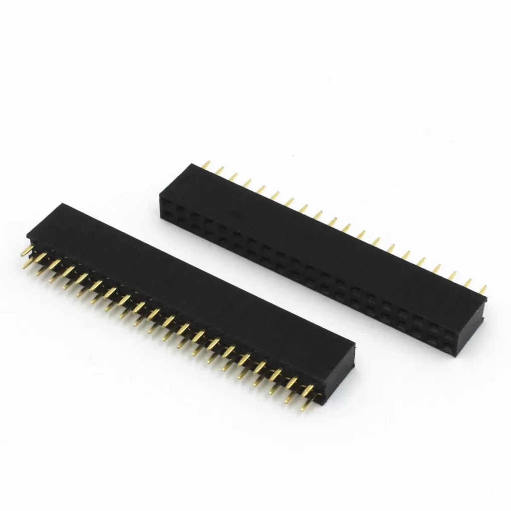
The 2.54mm pitch 40 pin connector header (also known as the Bergstik connector) is a classic and versatile board-to-board connection solution. Below...
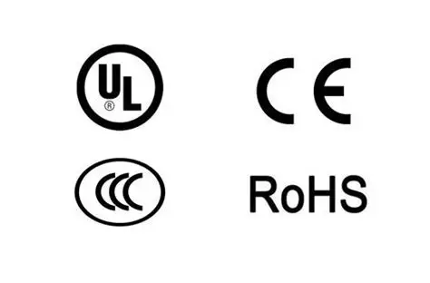
International standards and certifications in the pin header industry are crucial for ensuring the quality, safety, and compatibility of connector products. The...


