

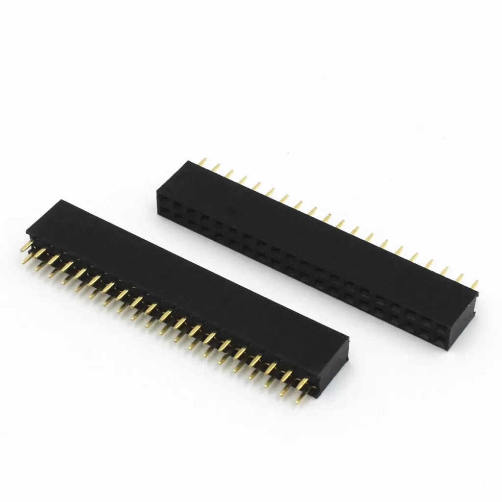
1.27mm Vertical SMT Pin Header — Compact Male Header with Brass Contacts & PA6T UL94V-0 Black Insulator for High-Density PCB Stacking & Board-to-Board Applications
This 1.27mm vertical SMT pin header is a compact male header connector designed for surface mount PCB applications where high-density interconnect and space-efficient board stacking are critical. Featuring precision-machined brass contacts with gold or tin plating and a PA6T UL94V-0 black thermoplastic insulator. Rated 1.0A per contact. This 1.27mm pitch male header PCB connector provides reliable board-to-board and wire-to-board connectivity in a footprint 50% smaller than standard 2.54 mm headers, making it ideal for compact consumer electronics, embedded systems, communication modules, and high-density industrial controllers. Bag/Tray packaging. Free sample available for qualified projects.
1.27mm Vertical SMT Pin Header — Product Overview
This 1.27mm vertical SMT pin header represents the optimal balance between contact density and manufacturing practicality for modern PCB interconnect applications. At half the pitch of the ubiquitous 2.54 mm (0.100″) header standard, the 1.27 mm (0.050″) pitch enables twice the contact count in the same PCB linear dimension — critical for space-constrained designs where every millimeter of board edge is contested by processors, memory, power management, and RF components.
Unlike through-hole pin headers that require drilled holes and occupy board space on both sides of the PCB, this high density SMT pin header brass configuration solders directly to surface pads using standard reflow processes. The vertical orientation positions pins perpendicular to the PCB surface, enabling direct mating with female socket headers, IDC ribbon cable connectors, or board-to-board interconnect systems. This SMT approach eliminates the need for secondary wave soldering operations, reduces PCB layer transitions, and enables denser component placement on the opposite board face.
The PA6T UL94V-0 black insulator material provides exceptional thermal stability for lead-free reflow soldering (withstanding peak temperatures up to 260°C), excellent dimensional stability across the operating temperature range, and V-0 flame retardancy for safety-critical applications. Brass contact material delivers the ideal combination of electrical conductivity, mechanical spring properties for reliable mating cycles, and cost efficiency for high-volume production. With a 1.0A current rating per contact, this header supports signal, low-power, and moderate-current applications in a single connector family, simplifying BOM management and procurement.
1.27mm Pitch Male Header PCB Connector — Full Technical Specifications
| Parameter | Value | Notes |
|---|---|---|
| Product Type | 1.27mm Vertical SMT Pin Header | Male header, surface mount |
| Part Number | PHC127 | Male header, surface mount |
| Pitch | 1.27 mm (0.050″) | Half of standard 2.54 mm pitch |
| Mounting Type | SMT (Surface Mount Technology) | Vertical orientation |
| Pin Orientation | Vertical (Perpendicular to PCB) | Standard board stacking direction |
| Current Rating | 1.0A per contact | At ambient temperature; derate at elevation |
| Contact Material | Brass | High conductivity, excellent spring properties |
| Contact Plating | Gold or Tin | Gold for high reliability; tin for cost efficiency |
| Insulator Material | PA6T (Polyamide 6T) | High-temperature thermoplastic |
| Flammability Rating | UL94V-0 | Self-extinguishing, safety compliant |
| Insulator Color | Black | Standard; other colors available on request |
| Contact Resistance | ≤ 20 mΩ | Initial value at rated current |
| Insulation Resistance | ≥ 1,000 MΩ | At 500V DC |
| Dielectric Strength | 500V AC / 1 minute | No breakdown or flashover |
| Mating Cycles | 200+ cycles (typical) | Dependent on plating and mating connector |
| Operating Temperature | −40°C to +105°C | Extended commercial / industrial grade |
| Storage Temperature | −40°C to +105°C | Long-term storage conditions |
| Reflow Soldering | Compatible | Peak 260°C, lead-free solder compatible |
| Packaging | Bag / Tray | Tape & reel available for automated assembly |
Why Engineers Choose the High Density SMT Pin Header Brass for Compact PCB Interconnect
1.27 mm Pitch — Double the Density of Standard 2.54 mm Headers
The 1.27mm pitch male header PCB connector provides twice the contact count per linear board edge compared to 2.54 mm headers. A 20-position 1.27 mm header occupies the same PCB edge length as a 10-position 2.54 mm header, enabling 40-pin, 50-pin, and 80-pin interconnects in footprints previously limited to 20, 25, or 40 pins. This density advantage is essential for compact embedded systems, FPGA development boards, and high-pin-count sensor modules.
Vertical SMT Mounting — Efficient Reflow Assembly & PCB Space Savings
The surface-mount vertical configuration eliminates through-hole drilling, reduces PCB layer transitions, and enables single-pass reflow assembly alongside other SMT components. The board to board vertical header 1.27mm orientation leaves the opposite PCB face free for additional components, battery placement, or shielding — critical in ultra-compact wearables, IoT sensors, and handheld instruments where Z-axis space is severely constrained.
1.0A Current Rating — Versatile for Signal and Low-Power Distribution
The 1.0A per contact rating supports digital signal lines (SPI, I2C, UART, GPIO), low-voltage power distribution (3.3V, 5V rails), and moderate current loads such as LED arrays, small motor drivers, and relay coils. For higher current requirements, parallel multiple pins or select our 2.0 mm or 2.54 mm header families with enhanced current capacity.
PA6T UL94V-0 Black Insulator — Reflow-Ready & Safety Compliant
The PA6T UL94V-0 black insulator withstands peak reflow temperatures up to 260°C without deformation, warping, or discoloration — essential for lead-free solder profiles. The V-0 flammability rating ensures self-extinguishing behavior within 10 seconds, meeting safety requirements for consumer electronics, automotive interior applications, and industrial control equipment. PA6T’s low moisture absorption maintains dimensional stability in humid environments, preventing contact misalignment after prolonged storage or tropical deployment.
Brass Contacts with Gold or Tin Plating — Optimized for Application & Budget
Precision-machined brass provides the ideal balance of electrical conductivity (≈28% IACS), mechanical strength for mating retention, and cost efficiency. Gold plating (typically 0.8–1.27 μm) delivers stable contact resistance, corrosion immunity, and extended mating cycle life for high-reliability applications. Tin plating offers excellent solderability and cost savings for static installations with limited mating cycles. Select plating based on your application’s reliability requirements, environmental exposure, and total cost targets.
RoHS Compliant & Production Ready
Fully compliant with RoHS Directive for lead-free manufacturing. The brass contacts with gold or tin plating provide excellent solder wetting with SAC305 and other lead-free solder alloys. Available in Bag/Tray packaging for prototype and manual assembly, with tape & reel options for high-speed pick-and-place equipment and automated optical inspection (AOI) systems.
Where to Use the Board to Board Vertical Header 1.27mm — Applications for Consumer, Industrial, Communication & Embedded Systems
Board-to-board interconnect in smartphones, tablets, digital cameras, portable media players, and handheld gaming devices where 1.27 mm pitch enables high-pin-count mating in minimal PCB area.
Sensor module headers, wireless communication module interfaces (Wi-Fi, Bluetooth, Zigbee, LoRa), and gateway expansion connectors where compact SMT assembly and reliable mating are essential for mass production.
Expansion headers on ARM Cortex development kits, Raspberry Pi HATs, FPGA evaluation boards, and microcontroller modules where the 1.27 mm pitch doubles GPIO capacity compared to 2.54 mm Arduino-style headers.
Backplane interconnects, daughter card headers, optical transceiver module connectors, and small cell radio interfaces where high contact density and signal integrity are critical for 5G and fiber optic infrastructure.
I/O module expansion headers, PLC communication interfaces, servo drive control connectors, and sensor array interconnects where industrial temperature range and reliable mating under vibration are required.
Infotainment module headers, ADAS sensor interconnects, body control module expansion ports, and EV battery management system communication interfaces where UL94V-0 flammability rating and extended temperature range are mandatory.
1.27mm Vertical SMT Pin Header — PCB Layout, Reflow Assembly & Signal Integrity Guidelines
Proper PCB design and assembly process control are essential to achieving optimal performance and reliability from this 1.27mm vertical SMT pin header. Follow these engineering best practices:
Footprint & Pad Design
- Use the manufacturer-recommended land pattern. The 1.27 mm pitch requires precise pad sizing and spacing to ensure proper solder joint formation, coplanarity, and mechanical stability. Verify the footprint against the official datasheet before PCB fabrication — even minor deviations can cause bridging, insufficient solder, or weak joints.
- Maintain adequate solder mask clearance between adjacent pads. At 1.27 mm pitch, the solder mask web between pads is typically 0.15–0.20 mm. Ensure your PCB fabricator can reliably achieve this fine web width to prevent solder bridging during reflow.
- Include polarity markings on the PCB silkscreen to indicate pin 1 orientation. Many 1.27 mm header applications involve high-pin-count connectors where reverse insertion would damage mating components or cause system malfunction.
- Consider castellated or extended pads for high-vibration applications. Extended pads provide additional solder volume and mechanical anchoring, reducing the risk of pad lifting or solder joint fatigue under mechanical stress.
Signal Integrity & Routing
- Route high-speed signals with care. At 1.27 mm pitch, adjacent signal traces must be extremely fine (typically 0.15–0.20 mm) to fit between pads. For high-speed digital buses (USB, SPI at high clock rates, parallel data), implement controlled impedance routing and maintain adequate spacing to prevent crosstalk.
- Stagger breakout patterns. For dense multi-row headers, consider staggered via placement or inner-layer breakout to reduce trace congestion near the connector. This improves manufacturability and signal integrity for high-pin-count interfaces.
- Implement ground return paths. For every signal pin, ensure a nearby ground return path — either through adjacent ground pins or through vias to the ground plane. This minimizes loop inductance and reduces EMI emissions, especially critical for clock and data lines.
- Power pin distribution: When using the header for power distribution, distribute power and ground pins across the connector rather than grouping them at one end. This reduces current crowding, minimizes voltage drop, and improves thermal performance under load.
Reflow Soldering Profile
- Peak temperature: 245–260°C (verify PA6T insulator specification for exact limit; most PA6T grades tolerate 260°C for 10 seconds)
- Preheat: 150–180°C for 60–120 seconds to activate flux and prevent thermal shock to the thermoplastic insulator
- Soak zone: 180–220°C for 60–90 seconds to ensure uniform component temperature and complete flux activation
- Ramp rate: ≤ 3°C/second to prevent component and PCB thermal stress
- Cooling: Controlled cooling at ≤ 4°C/second to ensure proper solder joint microstructure and minimize thermal shock to the PA6T housing
For automotive and high-reliability applications, follow IPC/JEDEC J-STD-020 moisture sensitivity level (MSL) requirements. PA6T has low moisture absorption compared to standard PA66, but proper storage in moisture barrier bags with desiccant is still recommended for MSL 2 or 3 rated components.
Mechanical & Mating Considerations
- Mating connector selection: Ensure the female socket header, IDC connector, or board-to-board mating component is designed for 1.27 mm pitch and compatible with the selected pin length and plating. Mismatched connectors can cause contact damage, increased insertion force, or intermittent connections.
- Pin length verification: Verify the exposed pin length above the insulator matches the mating connector’s contact engagement depth. Too short = unreliable contact; too long = mechanical overstress and potential bending.
- Board stacking height: For board-to-board applications, calculate the total stacking height including both PCBs, the header pin length, and the mating connector body. Ensure adequate clearance for components on both boards and any required shielding or thermal management.
For the official mechanical drawing, recommended PCB land pattern, 3D STEP model, and detailed reflow profile, please contact our sales team or request the product datasheet.
Quality Assurance & Manufacturing Standards
All Vistar pin header connectors, including this 1.27mm vertical SMT pin header, are manufactured under stringent quality management systems with comprehensive testing at every production stage:
- 100% dimensional inspection: Automated optical measurement confirms pitch accuracy (1.27 ± 0.05 mm), pin coplanarity (≤ 0.10 mm), pin straightness, insulator dimensions, and plating thickness
- Contact resistance testing: Statistical sampling confirms pin-to-pin resistance remains below 20 mΩ across production lots
- Plating thickness verification: X-ray fluorescence (XRF) measurement confirms gold or tin plating thickness meets specification on all contact surfaces
- Solderability testing: Wetting balance and dip-and-look testing per IPC/J-STD-002 to verify plating solderability after aging
- Reflow compatibility validation: Representative samples undergo three-pass reflow simulation to verify PA6T insulator dimensional stability and contact retention
- Mating force verification: Automated insertion/extraction testing with standard mating connectors to confirm mating force and contact retention within specification
- Environmental testing: Thermal cycling, humidity exposure, and salt spray testing to validate performance under challenging conditions
- RoHS & REACH compliance: Full material composition documentation and IMDS reporting available for regulatory compliance and international export
Our manufacturing facilities maintain ISO 9001 quality management certification with full lot traceability. Certificate of Conformance (COC), material safety data sheets, plating certification, and RoHS test reports are available upon request for customer qualification and audit requirements.
Engineering Resources & Related Pin Header Products
For comprehensive guidance on pin header selection, PCB interconnect design, and industry standards, explore these authoritative resources:
- Best Overview About 40 Pin Connector Header 2.54mm Male and Female — Comprehensive guide to the classic 2.54 mm Bergstik connector family, including pinout configurations, mating considerations, and application guidance for board-to-board and wire-to-board designs.
- The Main International Standards and Certifications in the Pin Header Industry 2025 — Expert analysis of UL, CE, CCC, RoHS, and other critical certifications governing pin header quality, safety, and environmental compliance in global markets.
Explore our full range of Pin Header Connectors for alternative configurations including 2.0 mm pitch, 2.54 mm pitch, single row, dual row, triple row, right-angle, U-type, double plastic, and custom pin-count options for your specific application.
1.27mm Vertical SMT Pin Header — Frequently Asked Questions
What is the difference between 1.27 mm and 2.54 mm pin headers, and which should I choose?
The primary difference is pitch (center-to-center spacing between adjacent pins) and the resulting contact density:
- 1.27 mm pitch: Half the spacing of 2.54 mm, enabling twice the contact count per linear board edge. A 40-pin connector occupies the same length as a 20-pin 2.54 mm header. Ideal for high-density applications where PCB area is severely constrained.
- 2.54 mm pitch: The de facto industry standard (0.100″), widely supported by breadboards, jumper wires, Arduino shields, and legacy equipment. Easier to hand-solder, more forgiving of PCB fabrication tolerances, and supported by a broader ecosystem of mating connectors and accessories.
Choose 1.27 mm when:
- PCB edge length is limited and high pin counts are required
- Product miniaturization is a primary design goal (smartphones, wearables, compact IoT)
- Automated SMT assembly is used (1.27 mm headers are rarely through-hole)
- Mating with 1.27 mm pitch FFC/FPC, mezzanine, or board-to-board connectors
Choose 2.54 mm when:
- Compatibility with existing breadboard, Arduino, or Raspberry Pi ecosystems is required
- Hand soldering or prototype rework is anticipated
- Higher current per pin is needed (2.54 mm headers typically support 3A+ vs 1.0A for 1.27 mm)
- Cost minimization is critical (2.54 mm headers are commodity items with aggressive pricing)
Many designs use both pitches — 2.54 mm for debug, programming, and expansion interfaces; 1.27 mm for internal high-density interconnects.
How does the PA6T insulator compare to PA66 or PBT for SMT pin headers?
PA6T (Polyamide 6T / Aramid) is a high-performance semi-aromatic polyamide specifically engineered for surface mount connector applications. Compared to standard materials:
- vs PA66 (Nylon 66): PA6T has significantly higher melting point (310°C vs 265°C), lower moisture absorption (1.5% vs 2.5% at saturation), and better dimensional stability after reflow. PA66 can warp or discolor during lead-free reflow at 260°C, while PA6T maintains structural integrity.
- vs PBT (Polybutylene Terephthalate): PA6T offers higher mechanical strength, better creep resistance under load, and superior solder heat resistance. PBT is lower cost and suitable for through-hole headers but may soften or deform during SMT reflow, especially for tall multi-row configurations.
- vs LCP (Liquid Crystal Polymer): LCP offers the highest thermal performance and lowest moisture absorption but at significantly higher cost. PA6T provides 90% of LCP’s reflow performance at 50–60% of the material cost, making it the sweet spot for most commercial and industrial SMT headers.
The PA6T UL94V-0 black specification used in this header combines the thermal and mechanical advantages of PA6T with V-0 flame retardancy, making it suitable for consumer electronics, automotive interior, and industrial control applications where both performance and safety compliance are required.
What is the maximum pin count available, and can I get custom configurations?
Standard 1.27 mm vertical SMT pin headers are available in single-row and dual-row configurations with pin counts ranging from 4 pins to 80+ pins per row. Common standard lengths include 10, 14, 16, 20, 26, 30, 34, 40, 50, and 60 positions per row. Dual-row configurations effectively double these counts (e.g., 2×20 = 40 total pins in the footprint of a 20-pin single row).
Custom configurations available upon request include:
- Modified pin counts: Any even or odd pin count within manufacturing limits
- Staggered or selective loading: Omit specific pins for keying, polarization, or signal isolation
- Custom pin lengths: Shorter or longer exposed pin lengths for specific mating connector requirements
- Alternative plating: Gold flash, selective gold over tin, or thick gold (3 μm+) for extreme reliability
- Color coding: White, red, blue, or green insulators for circuit identification or polarization
- Mounting pegs or polarization keys: Molded plastic pegs for additional PCB retention and insertion alignment
Contact our engineering team with your specific requirements for feasibility assessment, tooling lead time, and minimum order quantities.
What is the MOQ, lead time, and can I request a free sample?
Standard MOQ is 1,000 to 3,000 pieces depending on pin count and packaging specification, with a typical production lead time of 2–4 weeks. Free samples are available for qualified engineering evaluations, prototype builds, and new product development projects.
To request samples, contact sales@vistarelectronics.com with your company information, target application, estimated annual usage, preferred pin count, row configuration (single or dual), and plating preference (gold or tin). Alternatively, click the “Get a Quote” button at the top of this page to submit your inquiry directly.
For high-volume OEM customers and contract manufacturers, we offer tape & reel packaging for automated pick-and-place, custom pin counts and configurations, dedicated account management, and long-term supply agreements with volume pricing for programs with forecasted annual requirements above 50,000 pieces.
Is this header suitable for high-speed digital signals or RF applications?
The 1.27mm vertical SMT pin header is suitable for digital signals up to moderate frequencies (typically 50–100 MHz depending on trace length and termination). For standard microcontroller buses (SPI at 10–50 MHz, I2C at 400 kHz–3.4 MHz, UART, GPIO), the header introduces minimal signal degradation when proper PCB layout practices are followed.
However, for high-speed digital (USB 2.0+ at 480 MHz, MIPI, PCIe, Ethernet) or RF applications (Wi-Fi, Bluetooth, cellular), 1.27 mm pin headers are generally not recommended as the primary signal path due to:
- Impedance discontinuities: The pin-to-pin spacing and lack of controlled impedance in standard headers cause reflections at high frequencies
- Crosstalk: Tight 1.27 mm spacing between unshielded pins increases capacitive coupling between adjacent signals
- Stub effects: The vertical pin acts as an unterminated stub, creating resonances at GHz frequencies
For high-speed or RF applications, consider:
- High-speed board-to-board connectors with controlled impedance and ground shielding (e.g., Samtec Q Strip, ERNI MiniBridge)
- RF coaxial connectors (U.FL, IPEX, SMA) for antenna connections
- FFC/FPC connectors with ground-signal-ground routing for MIPI and LVDS
The 1.27 mm header remains excellent for power, control, and moderate-speed data in systems where high-speed signals use dedicated connectors.

2.54mm Pin Header SMT Double Row (PHC-254) | Dual Plastic PCB Board-to-Board Connector

2.54MM pin header double plastic SMT

2.0MM pin header three-row

2.0MM pin header U type

2.0MM straight pin header

2.54 pin header three row

2.54mm Pin Header Dual Row SMT Connector for High-Reliability PCB Applications

1.27MM pin header double row 90°

Market Trends and Prospects for Pin Header Connector in china Industry (2025-2030)
The industry of pin header connector in China is poised for steady growth from 2025 to 2030, driven by technological advancements and...
Best Overview About 40 Pin Connector Header 2.54mm Male and Female
The 2.54mm pitch 40 pin connector header (also known as the Bergstik connector) is a classic and versatile board-to-board connection solution. Below...
The Main international standards and certifications in the pin header industry 2025
International standards and certifications in the pin header industry are crucial for ensuring the quality, safety, and compatibility of connector products. The...