
In the electronics manufacturing industry, connectors are indispensable key components responsible for linking circuits and ensuring stable transmission of current or signals. FFC connectors (Flexible Flat Cable Connectors) and FPC connectors (Flexible Printed Circuit Connectors) are two common types of connectors, each with unique characteristics and application fields.
Brief Introduction of FFC Connector and FPC Connector
FFC connectors are commonly used to connect ribbon-like flat flexible cables (FFC) to PCB circuits in wire-to-board applications, and they can also be employed in wire-to-wire configurations. These connectors feature high density and an extremely narrow profile, making them suitable for tight spaces.
FPC connectors, on the other hand, are characterized by one end being soldered to the PCB (typically using SMT soldering) and the other end plugging into the FPC. Additionally, FPC connectors are designed with locking mechanisms to secure the FPC and ensure reliable contact.
Design Specifications
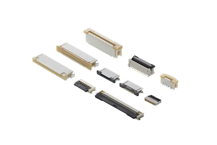
- FFC/FPC connectors offer options for pins, sockets, clamping edges, and solder tab contacts, available in single-row or double-row housings.
- Some variants support hybrid configurations, combining FFC cables and round wire contacts, with multiple pitch options such as 0.3mm, 0.5mm, 1.00mm, 1.25mm, and 2.54mm. The most common pitches are 0.50mm, 1.00mm, and 1.25mm.
- FFC/FPC connectors are available in fully shielded versions to mitigate EMC interference.
- Various locking mechanisms are provided to secure these connectors, including latches, locking pins, and retaining clips.
- Board termination options include surface-mount (SMT) or through-hole (THT) configurations

Difference between FFC connector and FPC connector
Structure
First, from a structural perspective, FFC connectors are primarily used to connect flexible flat cables (FFC). These cables consist of one or multiple rows of conductors separated by insulating material, resulting in a flat, flexible structure that is easy to bend and fold.
FPC connectors, however, are used to connect flexible printed circuits (FPC). FPC is a flexible substrate with printed circuits, allowing for the arrangement of various electronic components and circuits to achieve more complex connections.
Performance Characteristics
Second, in terms of performance characteristics, FFC connectors generally offer higher current transmission capacity, making them suitable for applications requiring high current flow. Due to their flat structure, FFC connectors also facilitate high-density connections, ideal for accommodating numerous conductors in limited spaces.
FPC connectors, meanwhile, place greater emphasis on signal transmission quality. They enable high-precision printed circuits on flexible substrates, ensuring stable signal transmission. Moreover, FPC connectors exhibit excellent resistance to bending and twisting, allowing them to adapt to various complex operating environments.
Application Fields
In terms of application fields, FFC connectors are widely used in electronic devices requiring flexible connections, such as displays, touchscreens, and keyboards. Thanks to the flexibility and bendability of FFC cables, they can easily connect various devices to transmit current.
FPC connectors, however, are more commonly employed in scenarios demanding high signal transmission quality, such as smartphones, tablets, and cameras. The printed circuit technology of FPC connectors allows for high-precision circuit layouts, ensuring stable performance in complex environments.
Cost Aspects
Finally, from a cost perspective, the prices of FFC and FPC connectors vary depending on factors such as materials, manufacturing processes, and application fields.
Generally, FFC connectors have relatively lower manufacturing costs due to their simple conductor structure. In contrast, FPC connectors, which require printed circuit technology, incur higher manufacturing costs. However, in practical applications, the choice between the two depends on specific requirements and budget considerations.

FFC Connector and FPC connector exhibit clear differences in structure, performance characteristics, application fields, and costs. In real-world applications, the appropriate connector type should be selected based on specific needs and scenarios to ensure circuit stability and reliability. With the continuous advancement of the electronics manufacturing industry, these two connector types are likely to undergo further optimization and innovation in the future, providing more efficient and reliable connection solutions for electronic devices.


