

3.5mm SMT DC Jack — 3.5×1.3mm Right-Angle PCB Power Connector
3.5mm SMT DC Jack — Product Overview
The DC-031A is designed for electronic products that require a compact external DC power connection on a printed circuit board. Its small 3.5×1.3mm interface is suited to applications where connector size, PCB area and enclosure space are important design considerations.
Unlike a vertical power socket, the right-angle configuration positions the mating interface toward the side of the PCB. This allows the external DC plug to enter from the edge of the board and can simplify alignment with a front or side enclosure opening.
The surface-mount construction also makes the connector suitable for PCB assemblies that use SMT production processes. Before mass production, engineers should verify the recommended PCB footprint, pad dimensions, component clearance and soldering conditions against the latest product drawing.
For power-input applications, connector selection should not be based on dimensions alone. The electrical rating, mating plug size, mounting configuration, mechanical life, insertion force, extraction force and enclosure interface all need to be considered together.
The combination of a compact 3.5×1.3mm interface, right-angle configuration and SMT mounting makes this connector suitable for a range of compact electronic products that use an external low-voltage DC power source.
Technical Specifications and Electrical Ratings
| Parameter | Specification | Engineering Notes |
|---|---|---|
| Part Number | DC-031A | Vistar catalog product |
| Connector Type | DC Power Jack | Female DC power receptacle |
| Pin Count | 4 Pins | Four-terminal connector configuration |
| Interface Size | 3.5 × 1.3 mm | Verify mating plug dimensions before production |
| Mounting Method | SMT / Surface Mount | PCB surface-mount construction |
| Orientation | Right Angle | Side-entry configuration |
| Rated Voltage | DC 30V | Maximum specified DC voltage |
| Rated Current | 0.5A | Maximum specified current rating |
| Insertion Force | 3–20N | Specified mating force range |
| Extraction Force | 3–20N | Specified unmating force range |
| Mating Life | 5,000 Cycles | Specified mechanical durability |
| Packaging | Bag / Tray | Production packaging options |
| Application | PCB DC Power Input | Compact electronic equipment |
Confirm all ratings and dimensions against the latest Vistar engineering drawing before PCB layout or mass-production approval.
3.5mm DC Power Jack — Matching the Plug to the PCB Connector
A 3.5mm DC power jack must be selected according to the dimensions of the mating DC plug. The nominal size of a barrel-style power connector does not always describe every mechanical dimension, so engineers should confirm both the outer and inner dimensions before approving the connector for production.
For the DC-031A, the specified interface is 3.5×1.3mm. The mating plug should therefore be checked against the manufacturer’s current dimensional drawing rather than selected only by visual similarity.
Correct mechanical matching is important for both electrical contact and reliable operation. An incorrect plug dimension can result in loose engagement, excessive insertion force, unstable electrical contact or difficulty removing the cable.
Polarity should also be checked during system design. A DC power connector can be mechanically compatible with a plug while still being unsuitable for the intended electrical configuration. The PCB circuit, power supply, cable and connector should therefore be reviewed as one complete power-input system.
For a broader explanation of DC barrel connector dimensions and selection factors, see Vistar’s DC barrel jack connector guide.
Why the 3.5×1.3mm Interface Matters
Small barrel interfaces are often selected when the finished product has limited enclosure space. The connector opening, mating plug and internal PCB position need to be considered together. This is particularly important for compact products where only a few millimeters of clearance may be available around the power-input area.
SMT DC Jack Right Angle — Board-Edge Installation
An SMT DC jack right angle configuration is useful when the external power cable needs to enter from the side of the PCB. Instead of positioning the plug perpendicular to the board surface, the right-angle arrangement directs the mating interface toward the board edge.
This configuration can simplify mechanical integration in products with a front-facing or side-facing power port. The PCB can remain relatively flat inside the enclosure while the connector opening aligns with the external housing cutout.
Right-angle connectors are commonly considered for compact consumer electronics, embedded equipment, control units and other PCB-based products where enclosure height is limited. However, the connector orientation should always be checked against the actual housing design.
PCB Edge and Enclosure Clearance
When placing a right-angle power jack, engineers should verify the distance between the connector and the PCB edge. The external housing opening should align with the connector centerline while allowing sufficient clearance for the mating plug.
Cable movement should also be considered. A plug that is repeatedly pulled sideways can transfer mechanical stress to the connector and solder joints. Where the finished product is expected to experience significant cable movement, the enclosure should provide suitable mechanical support around the power-input area.
Why Right-Angle Orientation Can Simplify Product Layout
The side-entry configuration can reduce the vertical space required above the PCB and make the external connector location easier to control. This is useful when the PCB is installed close to the top or bottom wall of a compact enclosure.
For this reason, connector orientation should be selected during the mechanical design stage rather than treated as a final PCB component decision.
3.5×1.3mm DC Jack — Dimensions, Mating and PCB Layout
The 3.5×1.3mm DC jack specification identifies the connector’s intended mating interface. For procurement and engineering approval, this dimension should be considered together with the complete mechanical drawing.
The connector’s overall body dimensions, terminal locations and mounting pads determine how it fits on the PCB. Even when the mating plug dimension is correct, an unsuitable PCB footprint can create assembly or enclosure problems.
Check the Complete Mechanical Drawing
Before releasing the PCB layout, engineers should verify the connector outline, terminal positions, recommended solder pads and board-edge relationship. The latest Vistar drawing should be used as the primary reference for production tooling and PCB design.
Check the Mating Plug
The corresponding plug should be tested with the production connector before mass production. Prototype testing can identify problems with insertion force, extraction force, plug length and physical interference that may not be obvious from a basic dimensional comparison.
Check the Enclosure Opening
The connector should also be evaluated with the final enclosure. The opening must provide sufficient clearance for the plug while keeping the connector properly aligned. For products assembled from multiple parts, tolerance stack-up should be included in the mechanical review.
Vistar’s barrel jack connector for power supply selection guide provides additional information on choosing DC connector dimensions and mounting configurations.
SMD DC Power Jack — SMT Assembly and Production Considerations
An SMD DC power jack can be a practical choice for products manufactured primarily with surface-mount components. The surface-mount construction allows the connector to be integrated into the PCB assembly process without using conventional through-hole mounting for the connector itself.
For production engineers, the PCB footprint should be verified before the component is released to the assembly line. Pad dimensions, component placement, solder coverage and neighboring component clearance all influence assembly quality.
SMT Placement
The connector should be positioned so that the placement equipment, PCB edge and enclosure design are compatible. Components close to the board edge require particular attention because the connector body and solder pads must remain within the approved board outline.
Soldering and Assembly Validation
Prototype assembly should be used to verify solder-joint quality and mechanical alignment. The production process should follow the connector manufacturer’s applicable assembly recommendations.
The electrical rating of the connector should also be reviewed under the actual application conditions. The DC-031A is specified at 30V DC and 0.5A. The finished product should operate within the connector’s rated conditions, while PCB traces, cables and the power source should be evaluated as part of the same circuit.
For applications requiring a different mounting style, Vistar offers additional DC power connector configurations. Compare the available products according to interface size, orientation, pin configuration and PCB mounting requirements rather than selecting solely by product name.
Key Features for Compact PCB Power Applications
3.5×1.3mm Interface
A compact mating interface for applications where the external DC power connection needs to fit within a limited enclosure area.
Right-Angle Configuration
The side-entry orientation allows the power cable to approach the connector from the PCB edge, supporting front or side enclosure openings.
Surface-Mount Construction
Designed for PCB surface mounting and suitable for product designs using an SMT-based assembly process.
30V DC / 0.5A Rating
The specified electrical rating supports low-power DC input applications when the complete system remains within the connector limits.
5,000 Mating Cycles
The specified mechanical life provides a defined reference for products where the power cable is repeatedly connected and disconnected.
Production Packaging
Bag and tray packaging options are available for engineering evaluation and production procurement.
Applications for the 3.5×1.3mm PCB Power Connector
Suitable for small electronic products requiring an external low-voltage DC power input.
Useful for compact controllers, gateways and embedded systems with board-mounted DC power input.
Suitable for electronic control units where a side-entry power connector is required.
Designed for applications operating within the specified 30V DC and 0.5A rating.
Useful for prototypes and test equipment requiring repeated connection and removal of an external DC supply.
Suitable for compact PCB assemblies where surface mounting and board-edge cable entry are required.
How to Select a Compact SMT DC Power Connector
Selecting a DC power connector should begin with the mating plug and electrical requirements. Once the interface size and electrical load are known, engineers can compare mounting method, orientation and mechanical characteristics.
1. Confirm the Interface Size
Start with the mating plug dimensions. The outer and inner dimensions must match the selected socket. For the DC-031A, the specified interface is 3.5×1.3mm.
2. Check Voltage and Current
The connector is rated at 30V DC and 0.5A. The application’s operating voltage and current should remain within the specified limits. Engineers should also review temperature, cable specifications and PCB trace capacity.
3. Select SMT or Through-Hole Mounting
SMT mounting can be advantageous when the PCB assembly is dominated by surface-mount components. Through-hole construction may be preferred where additional mechanical anchoring is required.
4. Select the Correct Orientation
Right-angle connectors are generally suitable for side-entry cables, while vertical connectors are used when the plug approaches perpendicular to the PCB. The enclosure should be considered before finalizing the orientation.
5. Validate the Mechanical Life
If the finished product will experience frequent cable connection and removal, mating-cycle requirements should be included in connector selection. This product is specified for 5,000 mating cycles.
6. Test a Production-Representative Prototype
Before mass production, test the actual mating plug, PCB, connector and enclosure together. This helps identify alignment, insertion-force, extraction-force and clearance problems before tooling and large-volume production.
SMT vs DIP DC Power Jacks for PCB Design
The mounting method is one of the first decisions engineers make when selecting a PCB power connector. SMT and DIP versions can both provide a reliable electrical connection, but they interact with the PCB and assembly process differently.
| Design Factor | SMT (DC-031A) | DIP / Through-Hole |
|---|---|---|
| PCB Mounting | Surface pads | Through-holes |
| Assembly Process | SMT production line | Wave, selective or manual soldering |
| PCB Drilling | No connector through-holes required | Requires drilled mounting holes |
| Board Layout | Useful for surface-mount layouts | Requires dedicated through-hole locations |
| Mechanical Design | Requires appropriate solder-pad and enclosure support | Through-hole terminals provide PCB anchoring |
| Typical Selection | Compact SMT assemblies | Applications emphasizing through-hole mechanical anchoring |
The appropriate mounting style depends on the product’s manufacturing process, PCB construction, enclosure, expected cable handling and mechanical requirements. The connector should be evaluated as part of the complete product rather than as an isolated component.
Mechanical Life and Plug Handling
A DC power connector can experience repeated mechanical loads during normal use. Every plug insertion applies force to the mating interface, while cable movement can introduce additional lateral loading around the connector.
This product is specified for 5,000 mating cycles. Engineers should compare that specification with the expected service conditions of the finished equipment.
The specified insertion and extraction force is 3–20N. During prototype evaluation, the actual mating plug should be tested with the production connector to confirm that the user experience and mechanical performance are appropriate for the application.
For products where the cable may be pulled or moved frequently, the enclosure can also help protect the PCB-mounted connector. Mechanical support around the connector opening can reduce unnecessary movement of the plug and connector assembly.
DC Power Jack Manufacturer for OEM and ODM Projects
Vistar Electronics supplies DC power connectors for OEM and ODM applications, including surface-mount and through-hole configurations. Product selection can be based on connector dimensions, mounting orientation, pin configuration, electrical rating and enclosure requirements.
For engineering projects, customers can provide the required connector size, mating plug specification, PCB mounting requirements, voltage, current and estimated annual volume. This information allows the appropriate connector configuration to be evaluated before production.
Vistar supports international electronics customers with engineering samples and production quantities. For qualified projects, customers can request product drawings and technical information for PCB and mechanical design verification.
For production sourcing, provide the required specification and estimated quantity when requesting a quotation. This is particularly important for projects where the connector needs to be matched to a custom PCB footprint or enclosure opening.
The complete Vistar DC Power Jack product category can be used to compare additional connector configurations.
Frequently Asked Questions About 3.5mm SMT DC Jacks
What is the DC-031A?
The DC-031A is a compact 4-pin SMT right-angle DC power jack with a 3.5×1.3mm mating interface. It is rated at DC 30V and 0.5A and has a specified mechanical life of 5,000 mating cycles.
What plug size is compatible with this connector?
The connector is specified for a 3.5×1.3mm interface. The mating plug should be checked against the current Vistar dimensional drawing to confirm the complete mechanical dimensions and compatibility before production.
Is this connector surface mount?
Yes. The connector uses SMT surface-mount construction and is intended for PCB mounting. The recommended PCB footprint and assembly conditions should be verified from the latest technical documentation.
What is the voltage and current rating?
The specified rating is 30V DC and 0.5A. The finished application should remain within the connector’s electrical limits and should also be evaluated for PCB trace, cable and operating-temperature conditions.
Is the connector right angle?
Yes. The connector uses a right-angle configuration, allowing the mating plug to enter from the side of the PCB. This configuration can simplify alignment with a front or side enclosure opening.
How many mating cycles are specified?
The connector is specified for 5,000 mating cycles. Actual service life depends on the mating plug, cable handling, environment and mechanical support provided by the finished product.
What is the insertion and extraction force?
The specified insertion and extraction force is 3–20N. Prototype testing with the actual mating plug is recommended before mass production.
Can Vistar provide samples?
Yes. Engineering samples are available for qualified projects. Contact sales@vistarelectronics.com with the connector specification, application and estimated quantity.
Can Vistar support OEM or ODM DC connector projects?
Yes. Vistar supports OEM and ODM connector projects. Customers can provide the required interface dimensions, mounting method, electrical specifications, mechanical requirements and estimated production volume for engineering review.
3.5mm SMT DC Jack — Complete Guide for Engineers and Procurement Professionals
What Is a 3.5mm SMT DC Jack?
A 3.5mm SMT DC jack is a surface-mount PCB power connector with a 3.5mm interface size and a right-angle configuration. The DC-031A is a 4-pin version rated for 30V DC and 0.5A, with a 3.5×1.3mm mating interface and a specified mechanical life of 5,000 mating cycles. Its surface-mount construction makes it suitable for automated PCB assembly and compact electronic equipment.
The 3.5×1.3mm interface is a small barrel-style DC connector size used in low-power electronic devices. The right-angle orientation places the port parallel to the PCB surface, allowing the DC cable to enter from the side of the enclosure. This is particularly useful in slim or compact products where vertical clearance is limited.
3.5mm DC Power Jack — Matching the Plug to the Connector
A 3.5mm DC power jack must be selected according to the dimensions of the mating DC plug. The nominal size of a barrel-style power connector does not always describe every mechanical dimension, so engineers should confirm both the outer and inner dimensions before approving the connector for production. For the DC-031A, the specified interface is 3.5×1.3mm.
Correct mechanical matching is important for both electrical contact and reliable operation. An incorrect plug dimension can result in loose engagement, excessive insertion force, unstable electrical contact or difficulty removing the cable. Polarity should also be checked during system design.
SMT DC Jack Right Angle — Board-Edge Installation
An SMT DC jack right angle configuration is useful when the external power cable needs to enter from the side of the PCB. Instead of positioning the plug perpendicular to the board surface, the right-angle arrangement directs the mating interface toward the board edge. This can simplify mechanical integration in products with a front-facing or side-facing power port.
When placing a right-angle power jack, engineers should verify the distance between the connector and the PCB edge. The external housing opening should align with the connector centerline while allowing sufficient clearance for the mating plug. Cable movement should also be considered, as repeated sideways pulling can transfer mechanical stress to the connector and solder joints.
3.5×1.3mm DC Jack — Dimensions and PCB Layout
The 3.5×1.3mm DC jack specification identifies the connector’s intended mating interface. For procurement and engineering approval, this dimension should be considered together with the complete mechanical drawing. The connector’s overall body dimensions, terminal locations and mounting pads determine how it fits on the PCB.
Before releasing the PCB layout, engineers should verify the connector outline, terminal positions, recommended solder pads and board-edge relationship. The latest Vistar drawing should be used as the primary reference for production tooling and PCB design. The corresponding plug should be tested with the production connector before mass production.
SMD DC Power Jack — SMT Assembly and Production
An SMD DC power jack can be a practical choice for products manufactured primarily with surface-mount components. The surface-mount construction allows the connector to be integrated into the PCB assembly process without using conventional through-hole mounting for the connector itself.
For production engineers, the PCB footprint should be verified before the component is released to the assembly line. Pad dimensions, component placement, solder coverage and neighboring component clearance all influence assembly quality. Prototype assembly should be used to verify solder-joint quality and mechanical alignment.
Applications Across Industries
This 3.5mm SMT DC jack is found across compact consumer electronics, IoT and embedded equipment, control electronics, low-voltage electronic devices, test equipment and PCB-based products. Its 3.5×1.3mm interface, right-angle orientation and 5,000-cycle life make it suitable for a wide range of compact electronic designs requiring reliable DC power input.
Why Choose Vistar as Your DC Jack Supplier
Vistar Electronics is a trusted manufacturer and supplier of DC power jacks serving customers in consumer electronics, industrial automation, and communication equipment. Our DC jack lineup includes SMT, DIP, right-angle, vertical, and panel-mount configurations with various pin counts, barrel sizes, and switching options.
With ISO 9001:2015 certification and a commitment to continuous improvement, Vistar is your reliable partner for high-quality power connector solutions. For more technical resources, including PCB layout guidelines and connector selection guides, visit our technical blog or contact our engineering support team directly.
Technical Reference and Industry Standards
For DC power connector qualification and international electronics production, the following official references provide useful background information:
- International Electrotechnical Commission (IEC) — standards for electrical and electronic equipment
- European Commission — RoHS Directive
- European Chemicals Agency — REACH
These references are provided for engineering and compliance background. The applicable requirements for the finished equipment should be determined according to the product category, destination market, and customer specifications.
Request a Sample or Quote for the DC-031A DC Jack
Need a compact 3.5mm SMT DC jack for a new PCB design? Contact Vistar Electronics with your required barrel dimensions, voltage, current, PCB mounting method, and estimated order quantity.
For the DC-031A, Vistar can provide product specifications and engineering samples for qualified projects. If the standard configuration does not match your enclosure or PCB, ask about OEM/ODM options for alternative connector configurations.
Product: 3.5mm SMT DC Jack
Part Number: DC-031A
Interface Size: 3.5 × 1.3 mm
Rating: DC 30V / 0.5A
Mounting: SMT Right Angle
Mating Life: 5,000 Cycles
DC-031A — 3.5mm SMT DC Jack | 3.5×1.3mm Right-Angle PCB Power Connector | RoHS & REACH Compliant | OEM/ODM Available

3.5*1.3 DC power jack dip 3pin

Female DC Jack 3pin DIP 90 Degree

Panel Mount DC Power Jack 5.5×2.5 — Reliable External Power Connection

Metal DC Jack Connector 3 Pin — DC-025 Through-Hole Metal Body DC Power Jack for PCB, Adapters & Industrial Power Supply

DIP DC Jack 5.5 2.1 — DC-044B Through-Hole DC Power Connector for PCB, Adapters & Industrial Power Supply

DC Power Jack 5.5×2.1mm — DC-012 Through-Hole Panel-Mount DC Power Connector for Adapters, Industrial & Consumer Electronics

DC Power Female Connector DIP 3 Pin — Through‑Hole PCB Mount DC Jack for Adapters & Industrial Equipment

5.5×2.5mm DC Power Connector – Jacks, Plugs & Panel Mount Solutions
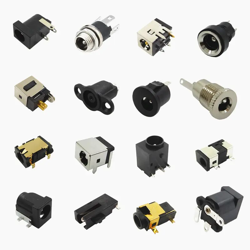
Barrel Jack Connector Selection and Usage Guidelines: Ensuring Reliable Power Delivery
Barrel Jack Connector for Power Supply — PCB Selection Guide: Sizing, Derating & Layout 2026 Choosing a barrel jack connector for power...

DC Barrel Jack Connector Guide: Types, Sizes & Selection Tips
A DC barrel jack connector is one of the most common — and most misunderstood — power connectors in electronics. Engineers specify...

5.5×2.1mm vs 5.5×2.5mm DC Jack: Critical Selection Guide
5.5×2.1mm vs 5.5×2.5mm DC jack selection looks simple until a prototype fails because the plug and socket do not make the correct...