
Choosing a barrel jack connector for power supply is a PCB design decision that involves more than matching the connector to a DC adapter. The jack must match the mating plug dimensions, supply voltage, operating current, polarity, mounting method, PCB footprint, enclosure clearance, and mechanical load created during repeated plug insertion.
For engineers designing a PCB power input, the most common problems are usually not caused by the basic connector concept. They come from selecting the wrong barrel size, using a current rating without adequate derating, creating an inaccurate PCB footprint, overlooking the switch terminal configuration, or placing protection components too far from the power entry point.
This guide focuses on those PCB-level decisions. It covers barrel jack size selection, current derating, polarity, TVS protection, switched contacts, PCB mounting, footprint considerations, and common layout failures.
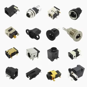
How to Select a Barrel Jack Connector for Power Supply
The best way to select a DC barrel jack connector is to start with the power source and the PCB requirements, rather than starting with the connector catalog.
Before choosing a part number, confirm the following:
- DC supply voltage
- Maximum continuous operating current
- Peak or startup current
- DC plug outer diameter
- DC plug inner diameter
- Plug insertion length
- Center-positive or center-negative polarity
- PCB mounting method
- Required connector height
- Available PCB space
- Enclosure and panel clearance
- Required mating cycles
- Operating temperature
- RoHS and REACH requirements
For OEM and ODM products, the mating plug should be specified together with the jack. A specification such as “DC jack, 5.5mm” is not sufficient because the inner contact diameter and mechanical configuration can vary.
A practical selection sequence is:
- Identify the mating DC plug.
- Confirm the outer and inner barrel dimensions.
- Confirm the power supply voltage and maximum current.
- Determine the required polarity.
- Select the mounting configuration.
- Check the PCB footprint and mechanical drawing.
- Review current derating and thermal conditions.
- Add input protection and verify the power-entry layout.
Barrel Jack Size: 5.5 × 2.1mm vs 5.5 × 2.5mm
Barrel jack size is one of the first specifications to verify because the jack must mate correctly with the DC plug.
A common specification such as 5.5 × 2.1mm describes a nominal 5.5mm outer barrel diameter and a 2.1mm inner contact diameter. A 5.5 × 2.5mm configuration has the same nominal outer diameter but a different inner contact dimension.
These sizes should not be treated as interchangeable. A plug and jack with different inner dimensions may still appear physically compatible, but the contact pressure and electrical connection can be unreliable.
| Barrel Size | Typical Selection | PCB Design Check |
|---|---|---|
| 5.5 × 2.1mm | Common DC power input | Confirm exact mating plug |
| 5.5 × 2.5mm | Common DC power applications | Do not substitute for 2.1mm without verification |
| 3.5 × 1.3mm | Compact electronic equipment | Check plug length and current rating |
| 4.0 × 1.7mm | Compact power interfaces | Verify mating dimensions |
For a production PCB, use the manufacturer’s mechanical drawing rather than creating a generic footprint based only on the barrel size.
Match the Barrel Jack Voltage and Current Rating
The electrical rating of a barrel jack connector for power supply should cover the real operating conditions of the product, including startup and transient current where applicable.
Check these parameters in the connector datasheet:
- Rated voltage
- Rated current
- Contact resistance
- Insulation resistance
- Withstand voltage
- Operating temperature
Do not select a connector solely because its nominal current rating matches the PCB’s normal load. Contact resistance generates heat, and connector performance can change with temperature, mating cycles, contamination, and mechanical conditions.
For example, a PCB that normally consumes 2A may experience a significantly higher current during startup. The selected connector should have sufficient margin for the expected operating profile rather than being operated continuously at its published maximum.
How to Derate a DC Barrel Jack Current Rating
A useful design approach is to select a jack with a current rating of approximately 1.5–2 times the maximum continuous operating current, while also checking the manufacturer’s actual derating curves and test conditions.
For example, if a circuit draws 2A continuously and can reach 3A during startup, a connector rated for approximately 5A provides additional current margin.
This margin reduces the risk of excessive resistive heating at the contact interface and gives the connector more operating headroom under real-world conditions.
However, the 1.5–2× value should be treated as a design rule of thumb, not a replacement for the manufacturer’s rating. If the connector datasheet specifies a lower rating at elevated temperature or under a particular mounting condition, use the manufacturer’s specification.
The complete power path should also be reviewed. The connector, PCB copper, fuse, protection device, input capacitor, MOSFET, and downstream regulator should all be sized for the same operating conditions.
Barrel Jack Polarity and Power Input Wiring
Barrel jack polarity must match the DC adapter. The most common arrangement is center-positive, where the center contact carries the positive supply and the outer sleeve is connected to ground or negative.
Center-negative configurations also exist, so polarity should always be verified from the power adapter and connector documentation.
For PCB design, clearly label the power input in the schematic and confirm the pin assignment from the connector drawing. Do not assume that the physical appearance of a barrel jack determines its electrical polarity.
If a switched barrel jack is used, the switch contact must also be identified correctly. The switched terminal is electrically different from the normal power and ground contacts and should be checked against the manufacturer’s pin diagram.
Adding TVS Protection at the DC Barrel Jack
The DC power jack is normally the first point where external power enters the PCB. This makes it a logical location for input protection.
A TVS diode can be used to clamp voltage transients between the positive power rail and ground. For component selection and transient protection design, see the Littelfuse TVS Diodes reference.
The selected TVS voltage must be coordinated with the normal supply voltage, maximum operating voltage, and the voltage tolerance of downstream components. A simple rule such as selecting a TVS with a nominal voltage 10–20% above the supply can be a starting point, but the actual standoff voltage, clamping voltage, pulse power, and expected surge waveform should be checked.
For example, a 12V input may use a TVS in the 15V class, such as an SMBJ15A, when its detailed electrical characteristics are compatible with the application.
A typical power-entry protection arrangement can include:
- DC barrel jack
- Fuse or resettable PTC
- Reverse-polarity protection
- TVS diode
- Input filtering capacitor
- Downstream DC/DC or power-management circuit
The exact order depends on the protection strategy. The fuse or PTC provides overcurrent protection, while the TVS addresses short-duration voltage transients. They perform different functions and should not be considered interchangeable.
Through-Hole vs SMT Barrel Jack for PCB Design
The mounting method has both electrical and mechanical consequences.
Through-Hole Barrel Jack
Through-hole barrel jacks are commonly selected when the connector will experience repeated plug insertion or cable movement. The terminals extend through the PCB and provide mechanical anchoring through the board.
This is particularly useful when the connector is positioned near the PCB edge and the user can apply axial or rotational force to the jack while connecting or removing the adapter.
For high-cycle applications, use all available mounting terminals and solder tabs specified by the connector manufacturer.
SMT Barrel Jack
An SMT barrel jack can simplify automated surface-mount assembly and may be appropriate where PCB assembly flow and board space favor a surface-mount solution.
However, the mechanical structure should be checked carefully. If the SMT terminals are responsible for both electrical connection and mechanical retention, repeated plug insertion can place significant stress on the solder joints.
Where possible, select an SMT jack with dedicated mechanical mounting tabs or other features designed to distribute insertion force.
Panel-Mount Barrel Jack
Panel-mount versions transfer much of the connector’s mechanical load to the enclosure. They can be useful when the power interface is exposed on the outside of the product and the enclosure provides sufficient mechanical support.
How to Use a Switched Barrel Jack for Battery Switching
A switched barrel jack provides an additional contact that changes state when the DC plug is inserted. This feature is often used in products that have both an external adapter and an internal battery.
The switch terminal can be used to detect adapter insertion or control the battery power path.
For battery-powered equipment, avoid assuming that the switch contact can carry the complete battery current. Many connector switch contacts have substantially lower current ratings than the main power contacts.
A common approach is to use the switch terminal as a control signal for a MOSFET-based battery disconnect circuit. In this arrangement, the mechanical switch controls the MOSFET gate rather than carrying the full battery current.
The actual circuit should be designed around the switch contact rating, MOSFET characteristics, battery voltage, and required power-path behavior.
Barrel Jack PCB Footprint and Layout
A correct barrel size does not automatically mean that the connector will fit the PCB. The barrel jack PCB footprint must be based on the exact mechanical drawing of the selected component.
Before releasing the PCB layout, verify:
- Terminal spacing
- Hole diameter
- Pad dimensions
- Connector body width
- Connector height
- PCB edge location
- Plug insertion clearance
- Enclosure clearance
- Nearby component keep-out area
- Mechanical mounting tabs
For through-hole connectors, verify both the drill diameter and pad diameter. For SMT versions, use the manufacturer’s recommended land pattern instead of scaling a footprint from a product photograph.
DC Barrel Jack Power Input Layout
The power-entry section should be designed as a complete circuit rather than placing the connector independently from the protection components.
Keep the high-current path between the barrel jack, protection components, and power-management circuit short and appropriately sized.
For a typical PCB power input, consider this general arrangement:
DC Barrel Jack
      ↓
Fuse / PTC
      ↓
Reverse Polarity Protection
      ↓
TVS / Input Protection
      ↓
Bulk Capacitor
      ↓
DC/DC Converter or Power Circuit
The exact arrangement depends on the system architecture. The important point is that transient protection and current protection should be placed close enough to the power entry point to limit the amount of unprotected PCB trace exposed to external disturbances.
High-current traces should also avoid unnecessary neck-down sections. Connector pins, vias, copper width, and thermal performance should be reviewed together when the input current is significant.
Common Barrel Jack Layout Failures
Wrong Plug and Jack Dimensions
A common failure is using a 5.5 × 2.1mm plug with a jack designed for a different inner diameter. The connector may appear to fit but can produce unstable electrical contact.
Connector Footprint Does Not Match the Mechanical Drawing
Using a library footprint without checking the manufacturer’s drawing can result in incorrect hole spacing, pad dimensions, body clearance, or PCB-edge positioning.
Connector Rated at the Exact Operating Current
Using a connector at its maximum published current leaves little margin for startup current, temperature variation, contact resistance, or long-duration operation.
Protection Components Placed Too Far Away
If the TVS diode or other input protection is located far from the connector, the section of PCB trace between the connector and protection circuit remains exposed to external transients.
Switch Contact Used for Excessive Current
The switch contact in a switched barrel jack may have a lower rating than the main power terminals. Routing the full battery or load current through the switch can exceed its specification.
Insufficient Mechanical Support
Repeated insertion and removal can stress solder joints and PCB copper. Use the mechanical mounting features specified by the connector manufacturer and consider enclosure support when appropriate.
Common Barrel Jack Sizes for Power Supply
Several barrel dimensions are commonly used for DC power input. The correct choice depends on the mating plug and the electrical and mechanical requirements of the product.
| Size | Typical Application | Selection Point |
|---|---|---|
| 5.5 × 2.1mm | General DC power input | Confirm plug compatibility |
| 5.5 × 2.5mm | DC power equipment | Verify inner contact dimension |
| 3.5 × 1.3mm | Compact electronics | Check current rating and plug length |
| 4.0 × 1.7mm | Compact power interfaces | Match the actual adapter |
For OEM and ODM projects, Vistar can also review customized connector dimensions, mounting configurations, pin arrangements, and other mechanical requirements.
Barrel Jack Selection Checklist for PCB Design
Before approving the connector for production, check the following items:
- Supply voltage
- Continuous current
- Peak and startup current
- Plug outer diameter
- Plug inner diameter
- Plug length
- Polarity
- Connector current rating
- Current derating
- Mounting method
- PCB footprint
- PCB edge clearance
- Enclosure clearance
- Switch contact rating
- TVS and input protection
- Mechanical retention
- Operating temperature
- Mating-cycle requirement
- RoHS and REACH compliance
Checking these items before PCB release can prevent a connector-related redesign later in the project.
Barrel Jack Connector for Power Supply: Final Design Check
For PCB power-input applications, the barrel jack should be specified as part of the complete power-entry system.
Confirm the mating plug dimensions, voltage, current, polarity, connector mounting configuration, PCB footprint, enclosure clearance, mechanical support, and protection circuit before the PCB is released.
If the product uses a switched barrel jack, verify the switch contact rating separately from the main power-contact rating. If the product has a battery, consider using the switch contact as a control signal for a MOSFET-based power path instead of routing the full battery current through the mechanical switch.
For higher-current designs, review connector derating, PCB copper, thermal conditions, and the complete power path rather than relying only on the nominal connector current rating.
As a barrel jack connector manufacturer, Vistar Electronics supplies DC power jacks for PCB and enclosure-mounted power input applications, including SMT, DIP through-hole, right-angle, panel-mount, and switched configurations.
Source DC Barrel Jack Connectors from Vistar Electronics
5.5×2.1mm, 5.5×2.5mm, and 3.5×1.3mm barrel jacks — SMT horizontal, DIP through-hole,
right-angle, and panel-mount. 3-pin switched variants available.
RoHS 3 compliant. MOQ 1,000 pcs. Free samples available.
DC Barrel Jack Selection — Frequently Asked Questions
How do I derate a DC barrel jack’s current rating?
What TVS diode should I use with a DC barrel jack?
Should I use through-hole or SMT for a DC barrel jack?
How do I use the switch terminal to disconnect a battery?
What causes intermittent power from a DC barrel jack?
Related DC Power Connector Resources
For the basic construction, sizing, polarity, and mounting options of DC barrel connectors, see our DC barrel jack connector overview.
For component selection and sourcing, visit the DC power jack product range.
For OEM or ODM requirements, including custom dimensions and mounting configurations, contact Vistar Electronics with your connector drawing or application requirements.
For a chassis-mounted external power inlet, see our
panel mount DC power jack 5.5×2.5mm.


