Learn the difference between SPDT vs DPDT slide switches, including circuit structure, wiring diagrams, and applications. Understand when to choose 3-pin SPDT or 6-pin DPDT slide switches for PCB design.
You are designing a control interface for a professional audio mixer. The product needs a switch that can route two independent audio signals simultaneously—left and right channels, switched together with a single actuator. The engineering team is debating between two options: a 3-pin SPDT switch or a 6-pin DPDT switch. The choice will determine whether the product requires two separate switches or one, whether the PCB routing is simple or complex, and ultimately whether the user experience is seamless or clumsy.
This is not a hypothetical. The slide switch is one of the most common electromechanical components in electronic design, yet the difference between SPDT and DPDT configurations is one of the most frequently misunderstood distinctions in switch selection. Both are widely used—SPDT switches are the most common slide switch configuration, while DPDT switches are essentially two SPDT switches operating in tandem. But they serve fundamentally different purposes, and choosing the wrong one means either a PCB respin or a product that cannot do what the customer needs.
For engineers, procurement professionals, and product designers, understanding the difference between SPDT and DPDT slide switches is not just technical knowledge—it is essential for making the right design decision from the start.
This guide breaks down the structural, functional, and application differences between SPDT and DPDT slide switches—including terminal configurations, wiring, typical use cases, and selection criteria.
What Is an SPDT Slide Switch?
SPDT stands for Single Pole, Double Throw. It is one of the most common switch configurations found in slide switches.
Structure:
- 3 terminals (one common, two output contacts)
- One circuit that can be switched between two outputs
- Change-over function (redirects the circuit)
An SPDT switch makes or breaks the connection of a single conductor with either of two other single conductors. It has three terminals: one common pin and two pins which compete for connection to the common. Rather than simply opening and closing a circuit, it redirects the circuit.
SPDT slide switches are available in 2-position (ON-ON) and 3-position (ON-OFF-ON) configurations. The 3-position variant adds a centre-off position, commonly used for forward-off-reverse motor control, three-state logic selection, or multi-function mode switching.
Key characteristics:
- Three terminal pins
- Switches between two output circuits
- Common terminal + two throw terminals
- Often referred to as a change-over switch
- Most common slide switch configuration
Typical applications:
- Selecting between two power sources
- Swapping inputs
- Basic signal routing
- Consumer electronics
- Low-voltage circuits
- Simple control functions
Advantages:
- Simple design
- Low cost and proven reliability
- Widely available
- Easy to design with
Internal link: Explore our SPDT Slide Switch options—available in 2-position and 3-position configurations.
What Is a DPDT Slide Switch?
DPDT stands for Double Pole, Double Throw. It is a more advanced switch configuration that provides control over two independent circuits simultaneously.
Structure:
- 6 terminals (two commons, four output contacts)
- Two independent circuits, each switchable between two outputs
- Equivalent to two SPDT switches operated by a single actuator
A DPDT switch is, in effect, the equivalent of two SPDT switches that operate in tandem. It has two separate poles, each able to connect to one of two output terminals. This allows the control of two independent circuits simultaneously.
DPDT switches are also known as 2P2T (2 Pole, 2 Throw) switches.
Key characteristics:
- Six terminal pins
- Controls two independent circuits
- Each pole switches between two outputs
- Single actuator operates both poles simultaneously
- More advanced version of SPDT
Typical applications:
- Audio equipment (stereo signal routing)
- Industrial controls
- Polarity switching (motor direction control)
- Dual signal routing
- Redundant circuit applications
- Machinery that alternates between operations
Advantages:
- Controls two circuits with one switch
- Reduces component count
- Ensures synchronous switching
- Can be used for redundancy
Important note: Industry experts do not recommend using two separate SPDT switches in lieu of one DPDT switch for any application. A single DPDT switch ensures the two circuits switch simultaneously, which is critical for applications like stereo audio, motor control, and safety-critical systems.
Internal link: Browse our DPDT Slide Switch —available in 6-pin configurations with multiple mounting options.
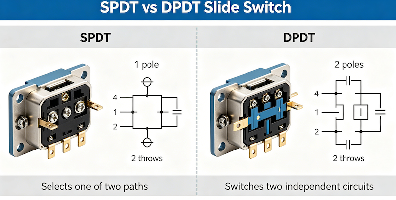
SPDT vs DPDT Slide Switch: Direct Comparison
| Feature | SPDT | DPDT |
|---|---|---|
| Terminals | 3 pins | 6 pins |
| Poles | 1 pole | 2 poles |
| Circuits Controlled | 1 circuit | 2 independent circuits |
| Function | Redirects one circuit between two outputs | Redirects two circuits between two outputs each |
| Equivalent To | Single change-over switch | Two SPDT switches in tandem |
| Complexity | Simple | More advanced |
| Cost | Lower | Higher |
| Common Configurations | ON-ON, ON-OFF-ON | ON-ON, ON-OFF-ON |
| Typical Applications | Signal selection, power source switching | Stereo audio, motor control, dual circuits |
SPDT vs DPDT Slide Switch: Key Differences Explained
Terminal Count and Circuit Control
The most immediate difference is the number of terminals and circuits controlled.
An SPDT switch has 3 terminals and controls a single circuit. It takes one input and redirects it to one of two outputs. Think of it as a single switch that chooses between two paths.
A DPDT switch has 6 terminals and controls two independent circuits. It takes two inputs and redirects each to one of two outputs. Think of it as two switches that move together.
Functional Capability
An SPDT switch is ideal for applications where you need to select between two options—two power sources, two signal paths, or two operating modes.
A DPDT switch is ideal for applications where you need to control two circuits simultaneously—stereo audio (left and right channels), motor direction (two windings), or dual signal routing.
When to Use SPDT Slide Switch
Choose an SPDT slide switch when:
- You need to select between two options (ON-ON)
- You need a centre-off position for three-state control (ON-OFF-ON)
- You are controlling a single circuit
- Cost and simplicity are priorities
- Your application is a basic consumer device
Common SPDT applications:
- Selecting between two power sources
- Swapping inputs
- Basic ON-OFF-ON control
- Low-voltage circuits
- Electric instruments and toys
When to Use DPDT Slide Switch
Choose a DPDT slide switch when:
- You need to control two circuits simultaneously
- You are routing stereo signals (left + right)
- You need polarity switching for motor direction control
- You require redundancy for safety-critical applications
- You want to reduce component count by using one switch instead of two
Common DPDT applications:
- Stereo audio equipment
- Industrial controls
- Machinery that alternates between operations
- Motor direction control
- Dual signal routing
Internal link: For more on slide switch configurations, see our Ultimate Slide Switch Guide .
SPDT vs DPDT Wiring Diagrams
SPDT Wiring
An SPDT switch has three terminals:
- Common (COM): The input terminal
- Normally Open (NO): Output 1
- Normally Closed (NC): Output 2
          ┌─── NO ─── Output 1
          │
Input ────┼─── Common (COM)
          │
└─── NC ─── Output 2- In one switch position, Common connects to NO
- In the other position, Common connects to NC
Example use: Selecting between two power sources. Connect the load to Common, and connect the two power sources to NO and NC.
DPDT Wiring
A DPDT switch has six terminals, arranged as two independent SPDT sections:
Circuit 1:   ┌─── NO1 ─── Output 1A
             │
Input 1 ────┼─── COM1
             │
             └─── NC1 ─── Output 1B

Circuit 2:   ┌─── NO2 ─── Output 2A
             │
Input 2 ────┼─── COM2
             │
└─── NC2 ─── Output 2B- The actuator moves both sections simultaneously
- In position 1: COM1 connects to NO1, COM2 connects to NO2
- In position 2: COM1 connects to NC1, COM2 connects to NC2
Example use: Stereo audio switching. Connect left audio to Circuit 1 and right audio to Circuit 2. One switch routes both channels simultaneously.
External link: For detailed switch wiring diagrams, see SparkFun’s Button and Switch Basics tutorial.
SPDT vs DPDT in PCB Design
When designing a PCB with slide switches, several considerations differ between SPDT and DPDT.
Footprint and Routing
SPDT:
- 3 pads (or 6 pads if using a 6-pin SPDT with dual common pins)
- Simple routing
- Minimal PCB space
- Easier to route in tight spaces
DPDT:
- 6 pads
- More complex routing (two independent circuits)
- More PCB space required
- Requires careful layout to avoid crosstalk between the two circuits
Mechanical Considerations
Both SPDT and DPDT slide switches are available in:
- Vertical mounting — actuator slides perpendicular to PCB
- Right-angle (horizontal) mounting — actuator slides parallel to PCB
- Surface Mount (SMT) — for high-volume automated assembly
- Through-Hole (DIP) — for maximum mechanical strength
Design for Manufacturing
- SPDT switches are easier to assemble and inspect
- DPDT switches require more attention during assembly to ensure proper orientation
- Both are available in tape-and-reel packaging for automated assembly
Internal link: Explore our Slide Switch Mounting Options —available in vertical and right-angle orientations with SMT and through-hole mounting.
SPDT vs DPDT: Which One Should You Choose?
| Requirement | Recommended Switch |
|---|---|
| Simple ON/OFF or select between two options | SPDT |
| Control a single circuit with two outputs | SPDT |
| Centre-off position needed (ON-OFF-ON) | SPDT or DPDT |
| Control two circuits simultaneously | DPDT |
| Stereo audio signal routing | DPDT |
| Motor direction control (polarity switching) | DPDT |
| Reduce component count | DPDT |
| Cost-sensitive, simple design | SPDT |
| Redundant circuit control | DPDT |
Decision Framework
Step 1: Count your circuits
- One circuit → SPDT
- Two circuits → DPDT
Step 2: Determine the switching function
- Select between two options → SPDT
- Control two independent paths → DPDT
Step 3: Consider PCB space
- Tight space → SPDT (fewer pins)
- Space available → DPDT (more capability)
Step 4: Evaluate cost
- Budget constrained → SPDT
- Performance priority → DPDT
Step 5: Think about future flexibility
- Simple, fixed function → SPDT
- Potential for dual-circuit control → DPDT
Common Mistakes When Choosing Slide Switches
Mistake 1: Confusing SPDT and DPDT
SPDT has 3 pins and controls one circuit. DPDT has 6 pins and controls two circuits. They are not interchangeable.
Solution: Count your circuits before selecting the switch.
Mistake 2: Using two SPDT switches instead of one DPDT
Industry experts do not recommend using two SPDT switches in lieu of one DPDT for any application. Two separate switches cannot guarantee synchronous switching.
Solution: Specify a single DPDT switch when you need two circuits switched simultaneously.
Mistake 3: Ignoring the centre-off option
Both SPDT and DPDT switches are available in 2-position (ON-ON) and 3-position (ON-OFF-ON) configurations. Choosing the wrong one can break your control logic.
Solution: Verify whether you need a centre-off position before finalizing the specification.
Mistake 4: Overlooking current and voltage ratings
Slide switches have maximum current and voltage ratings. Exceeding these ratings can cause contact welding or switch failure.
Solution: Always check the datasheet for electrical ratings. For high-power applications, use the switch to control a relay or transistor.
Mistake 5: Forgetting about actuator height
The actuator height (from PCB to the top of the slider) varies. A slider that is too short will not be accessible; one that is too long may interfere with the enclosure.
Solution: Account for panel thickness and user access when selecting actuator height.
Internal link: For help selecting the right slide switch, see our Slide Switch Selection Guide .
Related Switch Types
Beyond SPDT and DPDT, slide switches are available in other configurations:
| Switch Type | Terminals | Function | Common Use |
|---|---|---|---|
| SPST | 2 | ON-OFF | Simple power control |
| SPDT | 3 | Change-over | Signal selection, power source switching |
| DPST | 4 | Two independent ON-OFF circuits | Dual circuit power control |
| DPDT | 6 | Two independent change-over circuits | Stereo audio, motor control |
SP3T and DP3T switches are also available for applications requiring three positions or three output options.
Internal link: Explore our full range of Slide Switches —including SPST, SPDT, DPST, and DPDT configurations.
Frequently Asked Questions
What is the difference between SPDT and DPDT slide switches?
SPDT (Single Pole Double Throw) has 3 terminals and controls a single circuit, switching it between two outputs. DPDT (Double Pole Double Throw) has 6 terminals and controls two independent circuits simultaneously, with each circuit switching between two outputs.
Is DPDT just two SPDT switches?
Yes. A DPDT switch is essentially two SPDT switches that operate in tandem, controlled by a single actuator.
Which is better: SPDT or DPDT?
Neither is universally better. SPDT is better for simple, single-circuit applications where cost and PCB space are priorities. DPDT is better for applications requiring control of two circuits simultaneously, such as stereo audio or motor direction control.
Can DPDT replace SPDT?
Yes, a DPDT switch can be used as an SPDT switch by using only one pole and leaving the other pole unconnected. However, this is not cost-effective and wastes PCB space.
How many pins does SPDT and DPDT have?
SPDT switches have 3 pins (terminals). DPDT switches have 6 pins (terminals).
What is a slide switch used for?
Slide switches are used for controlling circuit current flow by sliding a lever or actuator back and forth. They are commonly used in low-voltage circuits for selecting between power sources, swapping inputs, and controlling electronic instruments and toys.
What is the difference between ON-ON and ON-OFF-ON slide switches?
ON-ON switches have two positions and switch between two circuits. ON-OFF-ON switches have three positions with a centre-off position, used for three-state control such as forward-off-reverse motor control.
Do you offer custom slide switch solutions?
Yes. Vistar Electronics supports OEM and ODM customization for slide switches, including actuator height, terminal style, packaging, and mechanical modifications. Contact our engineering team for specific requirements.
Slide Switches from Vistar Electronics
At Vistar Electronics, we understand the nuances of slide switch selection. Our slide switch portfolio includes:
- SPDT and DPDT configurations in 2-position and 3-position (ON-OFF-ON) variants
- Multiple mounting styles: Vertical and right-angle orientations
- Multiple termination styles: SMT and through-hole (DIP)
- Current ratings: 0.3A to 5A
- Mechanical durability: Up to 10,000 cycles
- RoHS and REACH compliant
- OEM and ODM customization available
Whether you are designing a consumer audio device, an industrial control panel, or a communication system, the right slide switch starts with understanding the difference between SPDT and DPDT. We can help you specify it, source it, and integrate it.
Internal link: Browse our full range of Slide Switches .
For technical specifications, samples, or application support, contact the Vistar Electronics engineering team.