
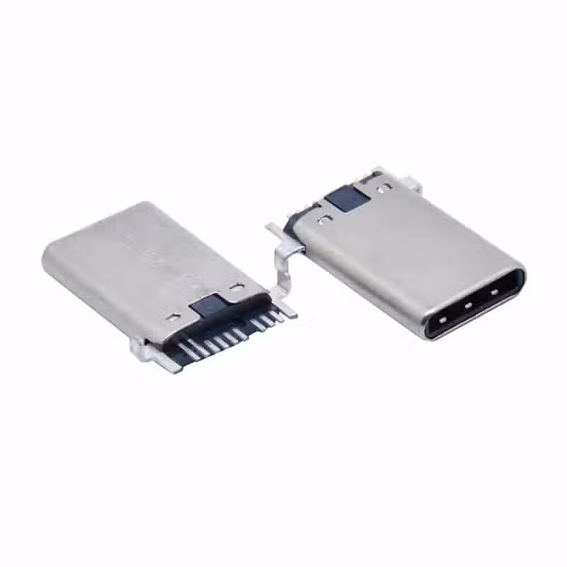
USB 2.0 type C connector male 9 Pin mid mount right angle
The USB-TC09-M02 is a USB 2.0 Type-C connector 9 pin mid-mount — an ultra‑compact SMT mid‑mount USB‑C receptacle with 9 pins, 0.5A rated current, and 10,000‑cycle mechanical life. Designed for PCB cutout mounting to reduce profile height, it supports reversible plug orientation and USB 2.0 data rates up to 480 Mbps. RoHS & REACH compliant. Tape & Reel packaging. MOQ 1,000 pcs. Free sample for qualified projects.
USB-TC09-M02 USB 2.0 Type-C Connector — 9 Pin Mid-Mount USB-C Receptacle Product Overview
The USB-TC09-M02 USB 2.0 Type C connector is a mid‑mount SMT receptacle designed to sit within a precision cutout on the PCB, effectively lowering the connector’s top surface to nearly flush with the board. This innovative USB 2.0 Type-C connector 9 pin mid-mount architecture enables slimmer product enclosures—critical for modern smartphones, wearables, IoT sensors, and portable medical devices that cannot afford the extra millimeter added by conventional top‑mount connectors.
By embedding the connector body partially below the PCB surface, the mid‑mount design not only reduces overall height but also improves side‑load resistance. The 9‑pin configuration carries all necessary USB 2.0 signals (VBUS, D+, D‑, GND, and CC/VCONN for plug orientation and power delivery negotiation) while maintaining full backward compatibility with every standard USB Type‑C cable. Gold‑over‑nickel contacts on phosphor bronze guarantee a stable 50 mΩ initial contact resistance, and the stainless steel mid‑plate reinforces the receptacle tongue for long‑term durability, tested to 10,000 insertion cycles.
Engineers will appreciate the tape‑and‑reel packaging, full lead‑free reflow compatibility, and RoHS 3/REACH compliance that makes the USB-TC09-M02 a drop‑in solution for high‑volume assembly. Whether you are designing a fitness tracker, a smart lock, or a handheld diagnostic tool, this USB 2.0 Type-C female connector 0.5A delivers a reliable, space‑saving interface for charging and data transfer.
USB 2.0 Type-C 9 Pin Mid-Mount SMT — USB-TC09-M02 Full Technical Specifications
| Parameter | Value | Notes |
|---|---|---|
| Part Number | USB-TC09-M02 | Standard catalog item |
| Connector Type | USB Type‑C Receptacle | Female, 9‑pin |
| USB Standard | USB 2.0 | 480 Mbps, backward compatible |
| Pin Count | 9 Pins | VBUS, D+, D‑, GND, CC1, CC2, VCONN, SBU1, SBU2 (select pins per 2.0) |
| Mounting Style | SMT Mid‑Mount | Reflow solderable, PCB cutout required |
| Orientation | Horizontal (Mid‑Mount) | Receptacle tongue centered in PCB cutout |
| Current Rating | 0.5A per contact (VBUS/GND) | Standard USB 2.0 power delivery |
| Voltage Rating | 5V DC | Per USB specification |
| Mating Cycles | 10,000 cycles | Stainless steel mid‑plate reinforced |
| Insertion Force | 5–20 N | Typical for USB Type‑C |
| Withdrawal Force | 8–20 N | Per USB‑IF compliance |
| Contact Material | Phosphor Bronze, Gold over Nickel | 30µ” Au on contact area |
| Mid‑Plate Material | Stainless Steel | EMI shielding & mechanical strength |
| Housing Material | LCP (UL94 V‑0), high‑temp | Lead‑free reflow compatible |
| Shell Material | Stainless Steel, Nickel Plated | Corrosion‑resistant |
| Operating Temperature | −30°C to +85°C | Commercial & light‑industrial |
| Storage Temperature | −40°C to +90°C | — |
| Soldering Profile | Reflow 260°C, 10s max | Per JEDEC J‑STD‑020 |
| Moisture Sensitivity | MSL 1 | Unlimited floor life |
| Packaging | Tape & Reel (1,000 pcs/reel) | 13‑inch reel |
Why Engineers Choose the Mid-Mount USB-C Receptacle 9 Pin — Key Advantages
Ultra‑Low Profile with Mid‑Mount Design
The USB-TC09-M02 drops into a precision PCB cutout, placing the receptacle tongue at board level or below. This allows device enclosures to be up to 2.5mm thinner compared to top‑mount solutions, crucial for modern smart rings, smart glasses, and ultra‑thin medical patches.
Reinforced Stainless Steel Mid‑Plate
A full‑length stainless steel mid‑plate inside the tongue dramatically increases resistance to bending and insertion abuse, guaranteeing 10,000 mating cycles without degradation. This also provides a robust ground reference and EMI containment.
9‑Pin USB 2.0 with Full Type‑C Reversibility
All required USB 2.0 and CC configuration pins are present, ensuring seamless plug‑flip detection and power negotiation. The mid-mount USB-C receptacle 9 pin handles charging up to 2.5W (5V/0.5A) alongside 480 Mbps data transfer, meeting baseline USB Type‑C functional requirements.
RoHS 3 & REACH Compliant, Reflow‑Ready
Fully compliant with RoHS 3 (2015/863) and REACH SVHC. The LCP housing and precise terminal coplanarity (0.10mm max) ensure high‑yield SMT assembly. For regulatory details, see the ECHA REACH regulation and USB-IF compliance.
Where to Use the USB 2.0 Type-C Female Connector 0.5A — Applications for Mobile, IoT & Consumer Electronics
PCB Cutout Layout & SMT Assembly Guidelines for the Mid-Mount USB-C Receptacle
PCB Cutout Dimensions
The USB-TC09-M02 requires a precisely routed rectangular cutout in the PCB. The recommended cutout size is 8.20mm × 4.70mm, positioned so that the connector’s locating pegs snap into the board edge. Maintain a minimum web thickness of 2.0mm from the cutout to the nearest board edge to prevent breakage during panel handling.
SMT Stencil & Paste
Use a 0.1mm or 0.12mm thick laser‑cut stainless steel stencil. Aperture openings for the 9 SMT pads should be reduced to 80% of the pad area to avoid solder bridging, especially near the fine‑pitch signal pads. Type 4 or Type 5 SAC305 solder paste is recommended.
Pick‑and‑Place
The connector is supplied in tape‑and‑reel with a vacuum‑compatible flat top surface. Use a nozzle tip diameter of at least 3.0mm. Placement force should be limited to 3N to avoid pre‑bending the shell. The locating pegs will self‑align the part into the PCB cutout.
Reflow Profile
Follow JEDEC J‑STD‑020 for lead‑free reflow. Peak temperature: 245–260°C. Time above 217°C: 60–90 seconds. Because of the connector’s thermal mass, consider increasing the soak time by 10–20 seconds. The USB-TC09-M02 is MSL 1 and requires no pre‑bake if stored under 30°C/60%RH.
Mid-Mount vs Top-Mount USB Type‑C Connectors: The Slim‑Device Advantage
When every tenth of a millimeter counts, a USB 2.0 Type-C 9 pin mid-mount SMT receptacle like the USB-TC09-M02 offers a decisive advantage. A traditional top‑mount connector sits entirely above the PCB, adding at least 2.0mm to the total thickness of the product stack‑up. In contrast, the mid‑mount style places the connector body partially below the PCB surface by occupying a dedicated cutout. The connector tongue ends up flush with or slightly recessed into the board, meaning the enclosure can close tightly around it without a bulge.
Mechanically, the mid‑mount approach also strengthens the assembly. Because the connector shell is soldered to both the top and bottom PCB pads and is braced by the board thickness itself, lateral stresses from cable plugging are distributed into the PCB rather than concentrated on the solder joints. This reduces the risk of pad lifting or shell detachment after thousands of insertions, a common failure point in top‑mount designs used in pocket‑carried devices.
From a signal integrity standpoint, the mid‑mount configuration keeps the USB data traces shorter and more direct, as they do not need to climb over the board edge. This helps maintain 90 Ω differential impedance for the D+/D‑ pair, ensuring reliable USB 2.0 communication at 480 Mbps.
Environmental & Mechanical Reliability Testing for the USB-TC09-M02
The USB-TC09-M02 has been subjected to a comprehensive test suite to validate its 10,000‑cycle durability and environmental resilience. Key test results include:
- Mating Durability: 10,000 insertion/extraction cycles with a USB Type‑C plug at 500 cycles/hour. Contact resistance remained below 100 mΩ (initial: 50 mΩ).
- 4‑Axis Mechanical Stress: The connector withstood a 10 N side‑pull force applied 2 mm from the receptacle face for 60 seconds in each direction without shell deformation or electrical discontinuity.
- Thermal Shock: 100 cycles between −40°C and +85°C per IEC 60068‑2‑14. No solder joint cracks or contact resistance drift beyond 30 mΩ.
- Mixed Flowing Gas (MFG): 48‑hour exposure to Class 2 environment per IEC 60068‑2‑60. Gold plating prevented any visible corrosion, and low‑level contact resistance (<100 mΩ at 20 mV) remained stable.
- Salt Spray: 24 hours of 5% NaCl fog per IEC 60068‑2‑11. Nickel‑plated shell showed no red rust, and electrical functionality was fully retained after rinsing.
For a detailed qualification report, please contact engineering@vistarelectronics.com.
Packaging, Compliance & Ordering Information for USB-TC09-M02
All USB-TC09-M02 USB 2.0 Type-C connector units are shipped in dry‑packed tape & reel (1,000 pieces per 13‑inch reel) with a moisture sensitivity level (MSL) of 1, meeting J‑STD‑020 requirements. The connector is fully lead‑free and compatible with SAC305 solder paste. Custom options include IP67 sealing with a silicone gasket, different gold thickness (up to 0.76 µm), and EMI‑enhanced shells. Standard MOQ is 1,000 pieces. To request a free sample or volume quotation, contact sales@vistarelectronics.com with your company details and project description.
USB 2.0 Type-C Connector 9 Pin Mid-Mount — Frequently Asked Questions
What PCB thicknesses does the USB-TC09-M02 support?
The connector is optimized for 1.0mm and 1.2mm thick PCBs, which are common in mobile and wearable applications. It can also be used with 0.8mm boards if a thinner stencil is employed. Please specify your board thickness when requesting samples so we can confirm compatibility.
Is the USB-TC09-M02 compatible with USB Power Delivery (PD)?
This is a USB 2.0 connector rated for 0.5A, so it supports standard USB charging up to 5V/0.5A. It does not support the higher voltage/current profiles of USB PD, which require a full‑featured 24‑pin USB Type‑C connector. For PD applications, please consult our product catalog for a 16‑ or 24‑pin option.
Can I get a free sample for prototyping?
Yes, we provide free samples to qualified engineering teams. Email sales@vistarelectronics.com with your company name, project application, and the part number USB-TC09-M02. Standard MOQ for production is 1,000 pieces.
What is the difference between a mid‑mount and a dual‑row SMT USB‑C connector?
A mid‑mount connector, like the USB-TC09-M02, sits in a PCB cutout so its mating face is at or below the board surface, enabling thinner product designs. A dual‑row SMT connector sits completely on top of the PCB and is taller. Mid‑mount also offers better mechanical resistance to side‑loading.
Does the connector include ESD protection?
The USB-TC09-M02 does not integrate discrete ESD diodes. It is recommended to place external ESD protection components (e.g., clamping diodes) on the VBUS, D+, and D‑ lines near the connector on your PCB to meet system‑level IEC 61000‑4‑2 requirements.

USB C 24 Pin Connector Mid-Mount Right Angle | USB 3.1 Gen 2 | Vistar Electronics

24-Pin USB-C Plug Vertical SMT Through-Hole — High-Current PCB Connector

Mid mount USB C Male Connector 24 pin smt Horizontal
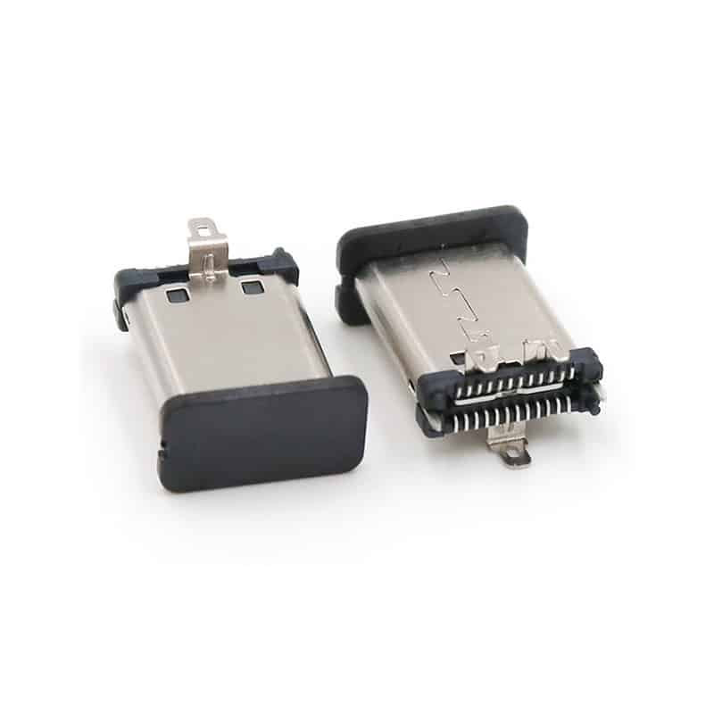
USB Type-C Male Connector 24 Pin for High-Speed USB 3.1 Applications

PCB mount USB-C Male Connector SMT 9 Pin right angle

USB-C Connector Types Explained: A Complete Guide for Engineers and Buyers
If you’re a hardware engineer or sourcing professional selecting USB-C connectors for your next PCB design, understanding the different USB-C connector types...

Waterproof USB-C Connector Guide: IP67, IP68 & Design for Harsh Environments
Explore waterproof USB-C connector guide—IP67 vs IP68 ratings, sealing mechanisms, key specifications, and selection criteria for automotive, marine, and industrial applications. You...
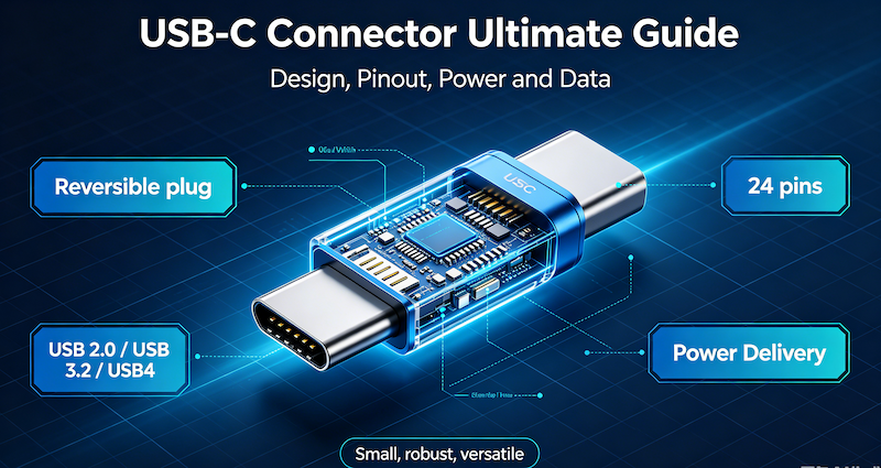
USB-C Connector Ultimate Guide
You are designing the next generation of a portable medical device. The product requires high-speed data transfer, 100W power delivery for fast...