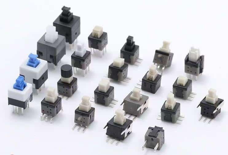
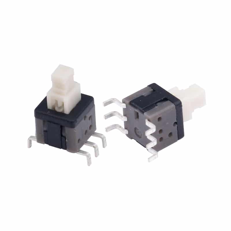
Push switches, a miniature switch commonly used in electronic devices. These push switches are known for their compact size and tactile feedback, making them suitable for applications where space is limited and a clear indication of activation is desired. They are available in various configurations, including momentary and latching (self-locking) types, and with different pin counts (e.g., 3-pin, 6-pin). A latching push switch, or a self locking push switch, which is a button that stays actuated and keeps the circuit closed even after you press it or pressure is removed from the button. It is a type of maintained push button switch;
- Momentary vs. Latching:
- Momentary(No-locking): The switch returns to its original position when released (e.g., like a button on a remote control).
- Latching (Self-Locking): The switch stays in the activated position until pressed again (e.g., like a light switch).
- Pin Configurations: 3-pin and 6-pin are common, allowing for different circuit connections and functionality.

1. Dimensional Specifications and Mechanical Characteristics
1.1 Precise Physical Parameters
- Exact dimensions: 5.8×5.8mm; 7x7mm; 8.5×8.5mm
- Actuation force: 160±50gf standard / 250gf heavy-duty variants
- Travel distance: 0.25±0.1mm pre-travel, 0.55±0.15mm total travel
- Terminal type: DIP/SMT (Surface Mount Technology) or through-hole configurations, Right-angle or Vertical types
1.2 Material Composition
| Component | Material Specification | Industrial Grade Alternatives |
|---|---|---|
| Housing | PBT (Polybutylene Terephthalate) | LCP (Liquid Crystal Polymer) |
| Contact Plates | Phosphor Bronze (0.2mm thick) | Beryllium Copper (high-cycle) |
| Actuator | Nylon 6/6 with glass fiber | Stainless steel plunger |
2. Electrical Performance Metrics
2.1 Standard Ratings
- Voltage capacity: 12VDC/24VDC (low voltage) to 50VAC/125VAC
- Current handling:
- 50mA minimum (signal circuits)
- 1A resistive / 0.5A inductive (power circuits)
- Contact resistance: ≤100mΩ initial / ≤200mΩ after lifecycle testing
2.2 Reliability Data
- Mechanical life: 100,000 cycles (standard)
- Electrical life: 50,000 cycles at rated load
- Operating temperature: -40°C to +85°C (extended range to +105°C)
3. PCB Integration Guidelines
3.1 Layout Recommendations
- Pad dimensions: 1.6mm × 1.2mm for SMT versions
- Keep-out area: 1mm clearance on all sides
- Soldering profile: 260°C peak temperature (Pb-free process)
3.2 Common Failure Modes
- Mechanical binding from excessive solder paste
- Contact oxidation in high-humidity environments
- Actuator deformation due to over-travel
4. Industry Applications(Common Applications:)
Medical Equipment:They are also found in medical monitoring equipment and other medical devices.
Consumer Electronics:These switches are frequently used in handheld devices, remote controls, calculators, and other small gadgets where a tactile and reliable button is needed.
Industrial Control Panels:Their durability and compact size make them suitable for control panels in machinery and industrial equipment.
Automotive Applications:They can be found in vehicle dashboards, electronic controls, and other automotive systems.
DIY Projects and Hobbyist Electronics:The switches are popular among hobbyists and makers for various electronic projects due to their ease of use and availability in different pin configurations (2, 3, and 6 pins).
Telecommunications and Networking:These switches are used in telecommunications equipment, networking devices, and server reset buttons.
5. Compliance and Certification
- Safety standards: UL 61058-1, EN 61058-1-1
- Environmental compliance: RoHS 3, REACH SVHC
- Automotive qualification: AEC-Q200 Grade 2 available

Selection and Implementation Checklist
- Verify required actuation force for user interface
- Confirm PCB thickness compatibility (0.8-1.6mm typical)
- Specify need for dust/water protection (IP40-IP67 options)
- Select appropriate terminal plating (Au flash vs. Sn coating)
