

4 Pin SMT DC Power Jack for Right-Angle PCB Mounting
4 Pin SMT DC Power Jack — Product Overview (4 Pin SMD DC Power Jack for Compact PCB Designs)
The DC-085 is a 4 pin SMT DC power jack — a right-angle surface-mount DC receptacle designed for compact PCB layouts where automated assembly and reliable power delivery are required. This 4 pin SMD DC power jack provides a secure interface for external DC power adapters, making it suitable for consumer electronics, industrial equipment, medical devices, and portable instruments.
This SMT DC power jack features four pins — two electrical contacts for power transmission and two mechanical anchor pins for enhanced PCB retention. The right-angle orientation positions the connector parallel to the PCB surface, enabling edge-mount installation that saves vertical space and simplifies enclosure design. The 4-pin configuration provides stable mechanical anchoring, reducing the risk of solder joint failure under repeated plug insertion and withdrawal.
Manufactured in an ISO 9001:2015 certified facility, this PCB mount DC power jack is fully compliant with RoHS 3 and REACH regulations. Available in tape-and-reel packaging for automated SMT assembly, with OEM customization options for volume orders.
SMT DC Power Jack — Full Technical Specifications
Below are the complete specifications for the SMT DC power jack DC-085, covering electrical, mechanical, and environmental ratings.
| Parameter | Specification | Notes |
|---|---|---|
| Part Number | DC-085 | Standard catalog item |
| Product Type | DC Power Jack | 4-pin SMT right-angle |
| Pin Count | 4 Pins | 2 electrical + 2 mechanical anchor |
| Mounting Type | SMT (Surface Mount) | Right-angle orientation |
| Orientation | Right Angle | Cable exit parallel to PCB |
| Voltage Rating | DC 30V Max | — |
| Current Rating | 0.5A | Centre pin (positive) |
| Insertion Force | 3–20N | — |
| Withdrawal Force | 3–20N | — |
| Mating Cycles | 5,000 cycles | Durability |
| Contact Material | Copper Alloy | Gold plated |
| Housing Material | High-Temperature Plastic | UL94V-0, reflow compatible |
| Operating Temperature | -25°C to +85°C | Commercial / industrial grade |
| Packaging | Reel / Tray | SMT assembly ready |
| Compliance | RoHS 3, REACH | Global export ready |
Specifications should be verified against the latest product drawing and engineering documentation before production release. Electrical performance depends on the complete power delivery system, including the connector, PCB layout, power supply, and load requirements.
PCB Mount DC Power Jack — Key Features and Advantages
4-Pin Configuration — Enhanced Mechanical Retention
Two electrical contacts for power transmission plus two mechanical anchor pins provide superior PCB retention compared to standard 2-pin or 3-pin DC jacks. This 4 pin SMT DC power jack design reduces the risk of solder joint failure under repeated plug insertion and withdrawal.
Right-Angle SMT — Space-Saving PCB Mounting
The right-angle orientation positions the connector parallel to the PCB surface, enabling edge-mount installation that saves vertical space and simplifies enclosure design. This right angle DC power jack is ideal for slim devices and compact electronics.
DC 30V / 0.5A Rating — Reliable Power Delivery
Rated for DC 30V and 0.5A, this PCB mount DC power jack is suitable for a wide range of low-voltage power applications, from consumer electronics to industrial equipment.
5,000 Mating Cycles — Long-Term Durability
Rated for 5,000 insertion and withdrawal cycles, this connector is built for applications requiring frequent connect/disconnect operations.
SMT Production Ready — Automated Assembly
Available in tape-and-reel packaging for high-volume pick-and-place assembly. The high-temperature housing withstands standard reflow soldering profiles.
RoHS 3 & REACH Compliant
Fully compliant with EU environmental directives. Documentation available for global export and supply chain audits.
4 Pin SMD DC Power Jack — Design and Selection Considerations
A 4 pin SMD DC power jack offers several advantages for PCB designers working on compact electronic devices. The four-pin configuration provides two electrical contacts for power transmission and two mechanical anchor pins for enhanced PCB retention. This design reduces the risk of solder joint failure under repeated plug insertion and withdrawal — a common failure mode in portable electronics and frequently connected devices.
When selecting a 4 pin SMD DC power jack for your design, consider the mechanical and electrical requirements of your application. The SMT termination supports automated reflow soldering, making it suitable for high-volume production. The right-angle orientation positions the connector parallel to the PCB surface, enabling edge-mount installation that saves vertical space and simplifies enclosure design.
For engineers designing portable devices, the 4-pin SMD DC power jack provides a reliable power interface that balances mechanical strength with manufacturing efficiency.
SMT DC Power Jack — Advantages for Automated Assembly
An SMT DC power jack is designed for surface-mount PCB assembly using automated reflow soldering processes. Compared with through-hole DIP versions, SMT DC power jacks offer several advantages for high-volume production. First, they eliminate the need for drilled through-holes, reducing PCB fabrication costs and increasing board density. Second, they support automated pick-and-place assembly, reducing labor costs and improving production consistency. Third, they are compatible with standard reflow soldering profiles, enabling efficient manufacturing workflows.
The SMT DC power jack is particularly well-suited for compact consumer electronics, portable devices, and applications where board space is at a premium. However, engineers should consider the mechanical requirements of their application — through-hole DIP versions may offer superior mechanical strength for applications subject to high cable pull forces or frequent plug insertion.
For a comparison of mounting options, see our DC Power Jack Connector Guide.
PCB Mount DC Power Jack — Layout and Footprint Guidelines
A PCB mount DC power jack should be selected according to both electrical and mechanical requirements. The connector needs to align accurately with the enclosure opening while maintaining enough clearance for the mating plug and cable. At the PCB level, the footprint must provide appropriate pads, mounting holes, grounding features, and routing space.
When designing the PCB footprint for this PCB mount DC power jack, engineers should consider the following:
- Pad size and shape: Follow the manufacturer’s recommended land pattern for optimal solder joint reliability.
- Anchor pin clearance: Ensure adequate clearance for the mechanical anchor pins to pass through the PCB.
- Component placement: Position the connector at the PCB edge with the port opening aligned to the enclosure cutout.
- Trace routing: Route power traces with adequate width for the rated current (0.5A).
The connector itself is only one element in the complete power delivery system. PCB trace geometry, component placement, and thermal management can all affect overall system performance.
Right Angle DC Power Jack — When to Choose Side-Entry Mounting
A right angle DC power jack positions the connector parallel to the PCB surface, enabling edge-mount installation that saves vertical space and simplifies enclosure design. This orientation is particularly useful in slim devices where vertical clearance is limited — such as portable electronics, set-top boxes, and compact industrial equipment.
The right-angle orientation offers several advantages over vertical mounting. First, it allows the connector to be placed at the PCB edge, with the port opening aligned to the enclosure side panel. Second, it reduces the connector’s height above the PCB, enabling thinner product designs. Third, it simplifies cable routing by allowing the power cable to enter from the side rather than the top of the device.
When designing with a right angle DC power jack, engineers should consider the mechanical clearance required for cable insertion and bending. Allow adequate space beyond the board edge for the connector body, cable plug, and cable strain relief.
SMT vs DIP DC Power Jacks — Which One Should You Choose?
When selecting a DC power jack for your PCB, understanding the differences between SMT and DIP mounting is essential. The table below compares the key characteristics.
| Feature | SMT DC Jack (DC-085) | DIP / Through-Hole DC Jack |
|---|---|---|
| Mounting Method | Surface mount — pads on PCB surface | Through-hole — pins pass through PCB |
| PCB Holes Required | No — surface pads only | Yes — drilled holes |
| Assembly Process | Reflow Soldering — automated | Wave / Selective Soldering |
| PCB Density | Higher — no through-hole clearance | Lower — requires hole clearance |
| Mechanical Strength | Good — pad design + anchor pins | Higher — dual-sided solder joints |
| Best For | Compact Electronics, High-Volume Production | Industrial Equipment, High-Reliability |
The DC-085 is an SMT connector. Choose this for compact PCB designs and automated assembly. For applications requiring maximum mechanical strength, consider our DIP / through-hole DC power jack options.
Where to Use This 4 Pin SMT DC Power Jack — Applications Across Industries
As a versatile 4 pin SMT DC power jack, the DC-085 is found across a wide range of applications where reliable right-angle SMT power connectivity is required. Its 4-pin configuration and right-angle orientation make it a preferred choice for engineers designing compact, high-volume electronic products.
4 Pin SMT DC Power Jack — Frequently Asked Questions
What is a 4 pin SMT DC power jack?
A 4 pin SMT DC power jack is a surface-mount DC receptacle with four pins — two electrical contacts for power transmission and two mechanical anchor pins for enhanced PCB retention. The DC-085 is a right-angle SMT version rated for DC 30V, 0.5A, with 5,000 mating cycles.
What is the difference between SMT and DIP DC power jacks?
An SMT DC power jack is surface-mounted on PCB pads using reflow soldering, making it suitable for high-volume automated assembly and compact PCB designs. A DIP / through-hole DC power jack uses pins that pass through drilled holes and are wave-soldered, providing higher mechanical strength. The DC-085 is an SMT connector — choose this for compact electronics and high-volume production.
What is the voltage and current rating of the DC-085?
The DC-085 is rated for DC 30V and 0.5A, making it suitable for a wide range of low-voltage power applications.
How many mating cycles does this connector support?
The DC-085 is rated for 5,000 insertion and withdrawal cycles, ensuring reliable performance in frequently connected applications.
What is the insertion and withdrawal force?
The DC-085 has an insertion and withdrawal force range of 3–20N, providing a secure connection while allowing easy plug insertion and removal.
Is this connector suitable for automated SMT assembly?
Yes. The DC-085 is designed for SMT assembly and is available in tape-and-reel packaging for high-volume pick-and-place machines. The high-temperature housing withstands standard reflow soldering profiles.
What is the MOQ and can I get a free sample?
Standard MOQ is 1,000 pieces with a 2–4 week production lead time. Free samples are available for qualified engineering and product development projects. Contact sales@vistarelectronics.com with your company details, project description, and part number (DC-085).
4 Pin SMT DC Power Jack — Complete Guide for Engineers and Procurement Professionals
What Is a 4 Pin SMT DC Power Jack?
A 4 pin SMT DC power jack is a surface-mount DC receptacle designed for PCB integration in compact electronic devices. The DC-085 features a right-angle orientation and four pins — two electrical contacts for power transmission and two mechanical anchor pins for enhanced PCB retention. This configuration provides reliable power delivery while maintaining mechanical stability under repeated plug insertion and withdrawal.
The 4-pin SMT DC power jack is commonly used in consumer electronics, industrial equipment, medical devices, and portable instruments where space is limited and automated assembly is required. The SMT termination supports reflow soldering, making it compatible with high-volume PCB assembly lines.
SMT vs DIP DC Power Jacks — Making the Right Choice
When selecting a DC power jack for your PCB, the choice between SMT and DIP mounting depends on your mechanical requirements and production volume. SMT DC power jacks are designed for automated reflow soldering processes. They are smaller, allow for higher-density PCB layouts, and significantly reduce assembly costs in high-volume production. However, they offer slightly lower mechanical pull-strength compared to through-hole versions.
DIP (through-hole) DC power jacks have pins that pass through the PCB and are soldered on the opposite side. They provide superior mechanical anchoring, making them ideal for products that experience frequent plugging/unplugging, heavy cables, or vibration. They are also easier to hand-solder for prototyping and low-volume production.
The DC-085 is an SMT connector. Choose this for compact PCB designs and automated assembly. For applications requiring maximum mechanical strength, consider through-hole DC power jack options.
Right-Angle DC Power Jack — When to Use It
A right angle DC power jack positions the connector parallel to the PCB surface, enabling edge-mount installation that saves vertical space and simplifies enclosure design. This orientation is particularly useful in slim devices where vertical clearance is limited — such as portable electronics, set-top boxes, and compact industrial equipment.
The right-angle orientation offers several advantages: it allows the connector to be placed at the PCB edge with the port opening aligned to the enclosure side panel; it reduces the connector’s height above the PCB, enabling thinner product designs; and it simplifies cable routing by allowing the power cable to enter from the side rather than the top of the device.
Applications Across Industries
This 4 pin SMT DC power jack is widely used across multiple industries. Consumer electronics use it for portable devices, set-top boxes, routers, and home entertainment equipment. Industrial equipment relies on it for control panels, automation systems, power supplies, and test instruments. Medical devices use it for patient monitors, diagnostic equipment, and portable medical instruments. Battery-powered devices, communication equipment, and lighting controls all benefit from the DC-085’s reliable right-angle SMT design.
PCB Layout Considerations
When designing with this PCB mount DC power jack, engineers should follow the manufacturer’s recommended land pattern for optimal solder joint reliability. The connector should be placed at the PCB edge with the port opening aligned to the enclosure cutout. Power traces should be routed with adequate width for the rated current (0.5A). The mechanical anchor pins require appropriate clearance on the PCB.
Why Choose Vistar as Your DC Power Jack Supplier
Vistar Electronics is a trusted manufacturer and supplier of DC power jacks serving customers in consumer electronics, industrial automation, medical devices, and communication equipment. Our DC power jack lineup includes SMT, DIP, right-angle, vertical, and panel mount configurations to suit various PCB layouts and production requirements.
With ISO 9001:2015 certification and a commitment to continuous improvement, Vistar is your reliable partner for high-quality interconnect solutions. For more technical resources, including PCB layout guidelines and connector selection guides, visit our technical blog or contact our engineering support team directly.
Explore our full range of DC power jacks and related content:
Need Custom DC Power Jack Solutions?
Vistar Electronics manufactures DC power jacks in SMT, DIP, right-angle, vertical, and panel mount configurations. Custom pin counts, plating, and packaging available for OEM projects.
DC-085 — 4 Pin SMT DC Power Jack | Right-Angle PCB Mount | RoHS & REACH Compliant | OEM/ODM Available

DC Power socket 3Pin DIP

DC Power Female Connector DIP 3 Pin — Through‑Hole PCB Mount DC Jack for Adapters & Industrial Equipment
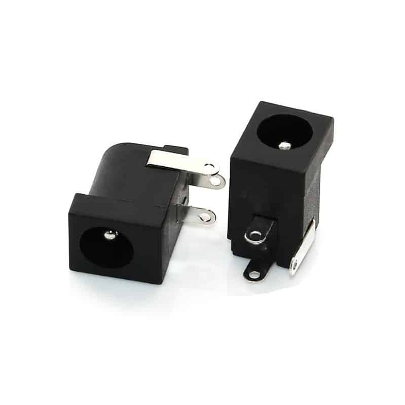
3 Pin DC Solder Connector – Through‑Hole Power Jack

3 Pin PCB Mount DC Jack — DC-013 DIP Vertical Female Power Connector for Consumer Electronics, IoT & Industrial Designs

Panel Mount DC Power Jack 5.5×2.5 — Reliable External Power Connection

3 Pin DC Power Jack Connector with Switch Function

Female DC Jack 3pin DIP 90 Degree

3.5*1.3 DC power jack dip 3pin
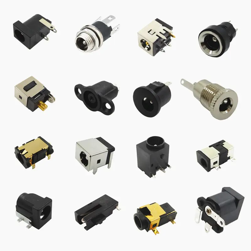
Barrel Jack Connector for Power Supply — PCB Selection Guide: Sizing, Derating & Layout 2026
Choosing a barrel jack connector for power supply is a PCB design decision that involves more than matching the connector to a...

5.5×2.1mm vs 5.5×2.5mm DC Jack: Critical Selection Guide
Choosing between 5.5×2.1mm and 5.5×2.5mm DC jacks is rarely the hard part — writing a BOM specification that a supplier can quote...

DC Barrel Jack Connector Guide: Types, Sizes & Selection Tips
A DC barrel jack connector is one of the most common — and most misunderstood — power connectors in electronics. Engineers specify...