D-Sub connector pins definitions and signal assignments vary significantly depending on the application area and industry standards.
The table below summarizes typical pin definitions from several key industries to help you quickly understand their diverse applications.
| Industry Applications | Typical Connector Models | Core Pin Definitions/Signal Assignments | Major Standards/Protocols Followed |
| Computer Communication (Serial Port) | DE-9 (often mistakenly called DB-9) | 1: CD (Carrier Detect), 2: RXD (Receive Data), 3: TXD (Transmit Data), 5: GND (Signal Ground), 7: RTS (Request to Send), 8: CTS (Clear to Send) | EIA/TIA-574 (RS-232) |
| Computer Communication (Parallel Port) | DB-25 | 1: /STROBE (Strobe), 2-9: D0-D7 (Data Bits), 10: /ACK (Acknowledge) | IEEE 1284 |
| Video Display (VGA) | DE-15 (3-row 15-pin) | 1: Red, 2: Green, 3: Blue, 13: Horizontal Sync (HSYNC), 14: Vertical Sync (VSYNC), 5/6/7/8/10: Ground | VGA Analog Video Standard |
| Professional Audio (Multi-channel Transmission) | DB-25 | typically allocates 24 available pins as either 8 channels of balanced analog audio (each channel consisting of a hot end, cold end, and ground) or 8 channels of AES/EBU digital audio | Customized by individual device manufacturers (e.g., Tascam, Digidesign, etc.) |
| Industrial Control (Example) | DB-9 (for CAN bus) | 1: CAN_H, 2: CAN_L, 3: GND, 4: +24V Power, 8: Shielding | ISO 11898 (CAN bus), J1939 |
| Military/Medical (Example) | DB-25 | Highly customized, typically including power partitioning (e.g., multiple pins in parallel to carry high current), differential signal pairs, redundant design, and dedicated diagnostic pins | MIL-DTL-24308 (Military) or industry device specifications |

Understanding the Design Philosophy Behind D-Sub Connector Pins Definitions
Beyond memorizing specific definitions, understanding the logic behind pin assignments in different applications can help you better design and troubleshoot systems.
- Computer Communication (RS-232): Its pin definitions are designed around the handshake protocol of serial asynchronous communication. Besides the basic TXD (transmit) and RXD (receive) data lines, pins like RTS, CTS, DSR, and DTR are used for flow control (handshake) and device status confirmation, ensuring coordinated operation between the modem (DCE) and computer (DTE). In a simple three-wire connection, typically only TXD, RXD, and GND are connected.
- Video Transmission (VGA): Its definition is very intuitive; the core is the transmission of analog signals. The three main RGB signals correspond to the brightness information of the three primary colors: red, green, and blue. Voltage changes control color brightness.
Horizontal sync (HSYNC) and vertical sync (VSYNC) signals control the scanning timing of the electron beam, ensuring the image is correctly displayed in the corresponding position on the screen. Multiple ground lines (GND) are used to provide reference grounds for their respective signals and reduce interference. - Professional Audio and Industrial Control: In these fields, the pin definitions of models like the DB-25 are usually manufacturer- or system-defined. Its core advantage lies in its integration, transmitting multiple signals through a single interface.
For example, in professional audio, one DB-25 interface can replace eight XLR or TRS interfaces, enabling the transmission of eight channels of balanced audio, significantly saving backplane space.
In industrial scenarios, the definition focuses on reliability and interference immunity, such as using twisted-pair differential signals (CAN_H/CAN_L) for the CAN bus, and allocating multiple parallel pins for power and ground to reduce impedance and improve reliability.

Important Selection and Usage Recommendations
In actual projects, correctly selecting and using D-Sub connectors is crucial.

- Confirming the definition is key: Due to the possibility of customization, always consult the device’s technical manual to determine the pin definitions; never connect based solely on experience.
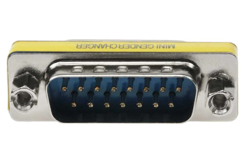
- Connector naming: Standard D-Sub naming should include a letter representing the housing size (e.g., A=15 pins, B=25 pins, C=37 pins, E=9 pins) and a letter representing the plug/socket (P for male, S for female). For example, a standard 9-pin connector should be called DE-9, not the commonly misused “DB-9”.
- Industrial Application Enhancement: In harsh environments, connectors with metal housings and screw-locking (often suffixed with S or W4) should be selected to ensure good electromagnetic shielding (EMI) and vibration resistance.
For corrosive environments or scenarios requiring higher protection, products made of specific materials (such as PPS plastic, 316L stainless steel) and plating (such as gold plating, sulfur-resistant silver plating) should be selected to achieve the required protection rating (such as IP68).
Hopefully, this detailed guide will help you clearly understand the specific applications of D-Sub connectors in different fields. If you have specific application scenarios or equipment models that require further discussion, I am happy to provide more specific reference information.