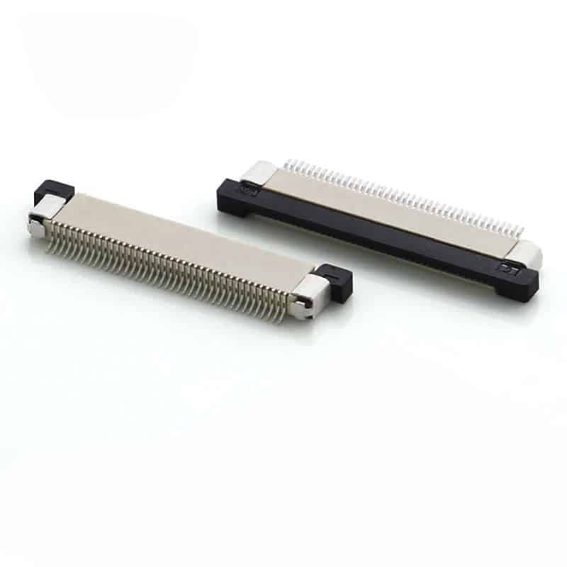
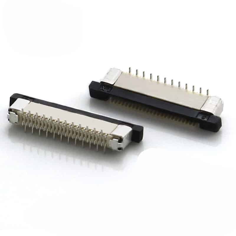
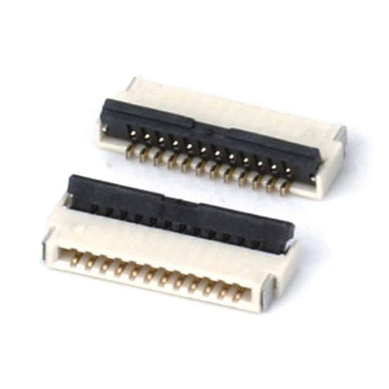
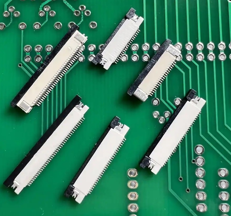
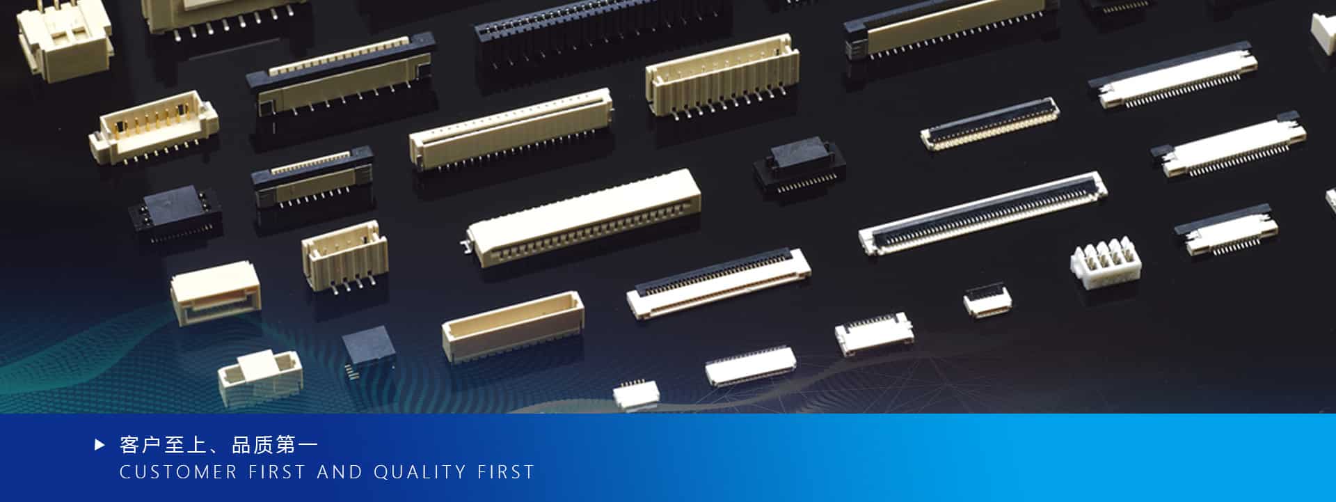
In the design of compact electronic devices, the selection of what seems to be a tiny FPC/FFC connector can determine the success or failure of a product. This article provides the ultimate guide, delving into the three core elements: Pitch, Actuator Type, and Contact Structure, to help you avoid design pitfalls, optimize your supply chain, and ensure product reliability and cost-effectiveness.
Introduction: Small Connector, Big Impact—Why a Wrong Choice is Costly
In today’s world of slim and compact electronics, from smartphone displays to drone camera modules, from laptop touchpads to sensors in portable medical devices, Flexible Printed Circuits (FPC) and Flat Flexible Cables (FFC) have become indispensable neural interconnects. The joints connecting these “nerves”—FPC/FFC connectors—are often underestimated in their importance.
An improperly selected connector can lead to a cascade of disastrous consequences:
- Field Failures: Intermittent signal loss, screen flickering, ultimately leading to product returns and brand reputation damage.
- Low Assembly Yield: Difficulty inserting the FPC, fragile latches breaking, leading to decreased production line yield and soaring costs.
- Repair Nightmare: Damaged connectors are often difficult to replace in the field, resulting in entire board scrappage.
The right selection decision is not just about choosing a small component; it’s about laying the foundation for your product’s reliability, manufacturability, and total cost of ownership. This guide simplifies the complexity by focusing on the three most critical decision points: Pitch, Actuator Type, and Contact Structure, to empower you to make the wisest choice.
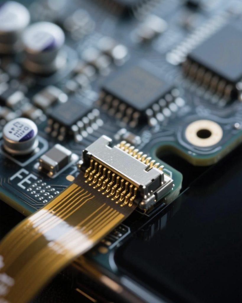
Chapter 1: Decoding Core Parameter 1: Pitch—The Art of Balancing Density and Cost
Pitch is the most fundamental parameter of an FPC/FFC connector, bar none. It refers to the distance between the center lines of adjacent contacts, directly determining the connector’s width and signal-carrying capacity.
1.1 Common Pitch Specifications and Their Applications
- 1.0mm Pitch:
◦ Characteristics: The earliest, most universal specification. The connector body and contacts are relatively robust, requiring lower precision.
◦ Applications: Where space constraints are not critical, signal count is low, and cost is extremely sensitive. E.g., some home appliances, children’s toys, simple power or low-speed signal transmission.
◦ Advantages: Lowest cost, high mechanical strength, easy to handle and assemble.
◦ Disadvantages: Largest volume, gradually being phased out in modern high-density designs. - 0.5mm Pitch:
◦ Characteristics: The current industry mainstream and de facto standard. Offers the best balance between density, reliability, and cost.
◦ Applications: Ubiquitous. Widely used in mobile phone displays, board-to-board interconnects, camera modules, tablets, drones, and most consumer and industrial electronics.
◦ Advantages: Good port density, mature supply chain, highly competitive price.
◦ Disadvantages: Requires reasonable assembly precision. - 0.3mm, 0.2mm and Finer Pitches:
◦ Characteristics: High-Density Interconnect (HDI) solutions. These connectors are extremely precise, demanding high standards for manufacturing, PCB layout, and FPC cable quality.
◦ Applications: Ultra-thin devices with extreme space constraints. E.g., inside hinges of foldable phones, ultra-narrow bezel displays in premium smartphones, minimally invasive medical devices, military-grade headsets.
◦ Advantages: Extremely high space efficiency, allows for more circuits on very narrow FPCs.
◦ Disadvantages: High cost, stringent requirements for PCB fabrication tolerances and FPC flatness, challenging assembly, often requiring high-precision automation.

1.2 Pitch Selection Decision Flow
- Assess Signal Requirements: First, determine how many signals need to be transmitted. 20 circuits? 40? This determines the required number of positions.
- Measure Physical Space: How much width does your design allow for the connector? Divide the available width by the number of positions to determine the maximum acceptable pitch.
- Weigh Cost vs. Manufacturing Capability: Ask: Can our factory reliably handle the assembly of a 0.3mm pitch connector? Can our FPC supplier guarantee the trace tolerances for such a fine pitch? If the answer is no, then opting for a 0.5mm pitch and slightly increasing the connector length might be a more robust and economical choice.
Chapter 2: Decoding Core Parameter 2: Actuator Type—ZIF vs. LIF, The Key to Reliability
The actuator is the connector’s latch. It determines how the FPC/FFC cable is inserted, locked, and removed. This is the most critical factor affecting connection reliability and assembly experience.
2.1 ZIF Connectors
- Working Principle: ZIF stands for “Zero Insertion Force.” In the open state, the contacts do not touch the FPC’s gold fingers at all. After inserting the FPC, flipping or sliding the actuator engages a cam or slider mechanism that applies pressure from above, clamping the FPC firmly against the bottom contacts, creating a stable connection.
- Advantages:
◦ High Reliability: Provides uniform and significant normal force, low contact resistance, excellent resistance to vibration and shock.
◦ Positive Feedback: A clear “click” or tactile feel when locked, helping operators confirm secure attachment.
◦ FPC Friendly: Minimal wear on the FPC gold fingers during insertion/extraction. - Disadvantages:
◦ Greater Height: The top-mounted actuator increases the connector’s Z-height.
◦ Slightly Higher Cost: More complex structure. - Types:
◦ Flip-Lock / Flip-Lever: Most common, operated by lifting and pressing a small lever. Ideal for manual assembly.
◦ Slider / Slide Actuator: Locked by sliding a small tab. May have a smaller side footprint.
2.2 LIF Connectors
- Working Principle: LIF stands for “Low Insertion Force.” It has no complex locking mechanism. The FPC is inserted and held primarily by friction, with the connector’s contact springs providing some retention force.
- Advantages:
◦ Ultra-Low Profile: Simple structure, resulting in a very low overall height, suitable for ultra-thin designs.
◦ Low Cost: Fewer parts, typically the most price-competitive.
◦ Fast Assembly: Direct insertion, no actuator manipulation. - Disadvantages:
◦ Reliability Risk: Limited retention force; risk of dislodgement under severe vibration or frequent mating cycles.
◦ Tolerance Sensitivity: Highly sensitive to FPC thickness tolerance; too thin causes poor contact, too thick makes insertion difficult or damages contacts.
◦ Insertion/Extraction Force: Although “Low Insertion Force,” repeated mating can still wear the gold fingers.
2.3 How to Choose: ZIF or LIF?
Follow this decision flow:
- Will your product be subjected to vibration or shock? (e.g., automotive electronics, portable devices, industrial tools) ◦ Yes -> Almost always choose ZIF. This is the best choice for ensuring connection integrity in harsh environments.
- Will the connector be mated/unmated multiple times during the product’s life? (e.g., serviceable parts, test ports)
◦ Yes -> Strongly recommend ZIF. The ZIF clamping mechanism is far less wearing on the FPC than the frictional insertion of LIF.( - Is your primary goal extreme thinness and the lowest cost?(e.g., disposable consumer products, mated once and rarely touched)
◦ Yes -> LIF can be considered. But rigorous vibration and mating cycle tests are mandatory, and FPC supply quality must be tightly controlled. - Is production assembly fully automated?
◦ Yes -> Both ZIF and LIF are possible. Automated equipment can precisely control insertion force and position. But ZIF still provides a more reliable lock confirmation signal. - Is it a production assembly manual?
◦ Yes -> ZIF is better. The tactile and auditory feedback from the flip lever significantly reduces operator error and improves first-pass yield.
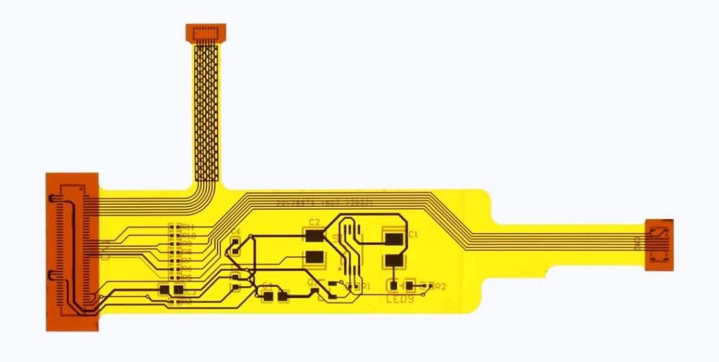
Chapter 3: Decoding Core Parameter 3: Top vs. Bottom Contact—The Deciding Factor for Spatial Layout
This choice concerns the connector’s orientation on the PCB, determining the FPC cable’s bend and routing direction.
- Top-Contact Connector:
◦ Definition: The contacts are located on the upper part of the connector body. When the FPC is inserted and locked, its gold fingers face up, parallel to the PCB.
◦ Routing Direction: The FPC cable exits from the top of the connector, usually requiring a downward bend for routing.
◦ Application: Useful when the FPC needs to route over other components or downwards to a lower level in the device. - Bottom-Contact Connector:
◦ Definition: The contacts are located on the lower part of the connector body. When the FPC is inserted and locked, its gold fingers face down, towards the PCB.
◦ Routing Direction: The FPC cable exits from the bottom of the connector, very close to the PCB surface, often allowing it to be laid flat directly on the board.
◦ Application: Very common, especially for connecting components that need to lie flat against the mainboard, like touchpads, daughterboards. It often enables a lower overall profile.
How to Choose?
This depends entirely on your mechanical structure and industrial design. Plan the FPC path early in the PCB layout phase. Ask: Which direction must the FPC cable go? Does it need to flip up or bend down?
Choose the contact type that allows the FPC to bend naturally and smoothly, avoiding sharp bends or twists. An unnatural bend creates stress, potentially leading to FPC fracture over time.

Chapter 4: Practical Selection Checklist: 5 Key Questions to Ask Your Supplier
Once you’ve narrowed down your options, when engaging with suppliers or distributors, be sure to ask these critical questions to ensure a foolproof selection:
- “Can you provide a complete 3D STEP model and detailed dimensional drawing?”
◦ Purpose: The most crucial first step. For checking mechanical interference and ensuring a perfect fit in your design. - “What is the recommended FPC thickness tolerance range for this connector?”
◦ Purpose: Confirm that your FPC supplier can meet the requirement. Mismatched thickness is a primary cause of poor contact. - “Is there mating cycle (durability) test data based on IPC standards?”
◦ Purpose: Understand the connector’s durability. For ports requiring frequent mating, insist on data guaranteeing at least 20-30 cycles. - “What is its performance data in vibration and mechanical shock tests?”
◦ Purpose: Assess its reliability in dynamic environments. Request to see relevant test reports. - “What is the material and thickness of the terminal plating on this connector?” (e.g., Gold plating, 0.2µm)
◦ Purpose: Plating affects contact resistance, oxidation resistance, and longevity. Thicker gold plating means better performance and durability in harsh environments, but at a higher cost.
Conclusion: A Framework for Informed Decision-Making
Selecting an FPC/FFC connector is not a simple act of checking a box on a parts list; it is a systematic engineering design decision. Please follow this framework:
- Start with the End Use: Begin with the product’s operating environment, life expectancy, and physical constraints.
- Prioritize: Define your primary goal—is it reliability first, cost first, or thinness first?
- Co-Design: Consider connector selection, FPC design, and PCB layout as an integrated whole. Do not make decisions in isolation.
- Test, Test, and Test Again: Before mass production, comprehensive reliability testing—including vibration, mating cycles, and temperature cycling—is absolutely essential.
With this guide, you are now equipped with the knowledge to make this critical decision. You can now engage with suppliers confidently and select the most suitable FPC/FFC connector for your next innovative product, laying a solid foundation for its success.


