
D-Sub connectors ( d subminiature connectors) continue to hold a vital position in industrial automation due to their robustness, reliability, and interference immunity. The table below summarizes their main application scenarios and key cabling standards to help you quickly understand the core information.

| Application Area | Specific Role and Function | Key Cabling Standards |
| Industrial Robot Control | Connects joint drive motors, sensors, and control systems, transmitting power and precise control signals. | Focus on vibration resistance and signal integrity. |
| PLC System Communication | Serves as a serial communication interface for traditional equipment such as RS-232/RS-485/Modbus, connecting PLCs, HMIs, frequency converters, etc. | Pay attention to signal attenuation and grounding. |
| Elevator Control System | Connects the car control panel, floor display, drive motor, and safety system, transmitting commands and status feedback. | Emphasis is placed on vibration resistance and mechanical durability. |
| High-Precision Equipment (e.g., 3D printers) | In high-temperature, high-speed printing environments, connects the nozzle control system, feeding system, and data interface to ensure accurate command transmission. | Consider high-temperature resistance and signal stability. |
Core Cabling Specifications Explained
Proper cabling is crucial for ensuring the stable operation of DB connectors in harsh industrial environments. The following are key technical specifications to focus on:
1. Connector Handling and Electromagnetic Shielding
- Select Metal-Shelled Models: D-Sub connectors with metal shells must be selected; this is fundamental for achieving electromagnetic shielding.
- 360-Degree Shielding Connection: The cable shielding layer must achieve a 360-degree surround connection with the connector’s metal shell via a metal conductive pad or crimping. Experiments show that this method can effectively attenuate high-frequency interference by more than 40dB. Avoid using a “pigtail” connection for the shielding layer, as this will significantly reduce its effectiveness.
2. Cable Selection and Laying
- Cable Selection: Shielded twisted-pair cable should be used, with a shielding coverage of at least 85%. For switching signals, AWG18-22 cables are commonly used.
- Laying Spacing: Signal cables should be laid separately from power cables (such as motor drive lines), with a minimum spacing of 30 cm. Engineering practice shows that this can reduce interference voltage to 1/10 of its original value. If crossing is unavoidable, it should be at a 90-degree right angle.
- Layering Principle: When laying cables in cable trays, the layering principle of “signal lines on top, control lines in the middle, and power lines at the bottom” should be followed. Different types of cables should ideally be separated by metal partitions.
3. Grounding System Optimization
- Single-Point Grounding: To avoid ground loop interference, a single-point grounding architecture is recommended. Typically, the shielding layer is grounded at one end at the receiving end.
- Independent Grounding Electrode: Near high-interference equipment such as frequency converters, an independent grounding electrode should be set up for signal grounding. The grounding resistance should be less than 4Ω.
4. Anti-interference and Interface Enhancement Design
- Signal Pin Protection: Add TVS diodes to the front end of critical signal pins (such as RXD/TXD of RS-232) to prevent surge impact; or connect ferrite beads in series to suppress high-frequency noise.
- Power Supply and Grounding Enhancement: For power supply pins, multiple pins can be connected in parallel to increase current carrying capacity. Grounding pins are also recommended to be connected in parallel with multiple pins, and star grounding or dual-point grounding should be used to reduce grounding impedance.
- Functional Zoning: When defining custom pins, power, signal, and grounding pins should be strictly separated into different zones. Maintain appropriate spacing between different types of pins (e.g., ≥3mm), and increase the proportion of grounding pins (recommended to exceed 30%) to improve isolation.
Installation, Maintenance, and Common Misconceptions
1. Installation Operation Points
Tightening Screws: After plugging and unplugging the connector, be sure to tighten the fixing screws on both sides of the connector. This is crucial for its vibration resistance.
Preventing Mis-Mating: Utilize the inherent D-shaped structure of the D-Sub connector to prevent mis-mating. Pay attention to pin alignment and do not use excessive force.
Soldering/Crimping Quality: Ensure reliable termination quality and avoid cold solder joints or poor soldering. Use a backshell to provide additional mechanical stress protection for cable connection points.
2. Maintenance and Troubleshooting
Regular Inspection: Establish a regular inspection system, focusing on checking connectors for physical damage and oxidation, loose screws, and the integrity of the cable shielding.
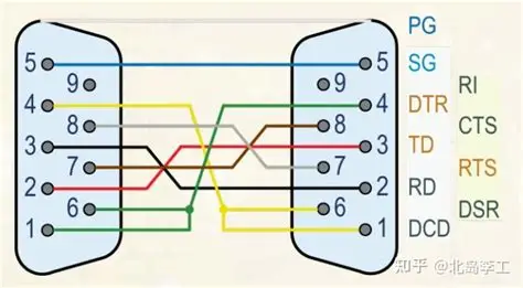
Common Faults: In case of communication interruptions or bit errors, check the following in sequence: Screws tightened; pins bent or damaged; wiring sequence conforming to pin definitions (refer to a standard definition table such as DB9); and shielding grounding.
3. Common Mistakes to Avoid
Avoid Omitting the Shielding Layer: Never omit the shielding layer or leave it suspended in interference environments.
Avoid Bundling with Power Lines: Never bundle D-Sub signal cables and power cables in the same harness.
Avoid Neglecting the Screws: Do not leave the screws loose after inserting the connector.
Avoid Exceeding Electrical Limits: Pay attention to the connector’s voltage and current ratings; never use it to drive high-power motors or other loads beyond its capacity.
Summary
The vitality of connector sub D in industrial automation stems from their robust mechanical structure, reliable screw fastening method, excellent electromagnetic shielding performance, and significant cost-effectiveness.
By adhering to strict wiring standards, especially in shielding, grounding, and installation details, they can consistently provide stable and reliable connectivity for industrial automation systems.
We hope these specific application examples and detailed wiring guidelines will be helpful to your work. If you encounter more unique situations in your projects, please feel free to raise them, and we can continue to discuss them in depth.

