
The D Sub connector, an interface that has played a crucial role in the history of electronic devices and computers, ensures a stable and reliable connection with its iconic D-shaped metal shielding shell. Despite facing challenges from emerging interfaces, it continues to play a key role in specific fields.
The table below summarizes the core information of the D-Sub connector, helping you quickly grasp its overall characteristics.

| Feature Classification | Detailed Description |
| Name Origin | Derived from its D-shaped metal shielding shell, this structure effectively prevents accidental insertion and removal and provides a certain degree of electromagnetic shielding. |
| Invention Background | Invented by Cannon (now part of CanT) in 1952, it was initially called “D-subminiature” due to its relatively small size at the time. |
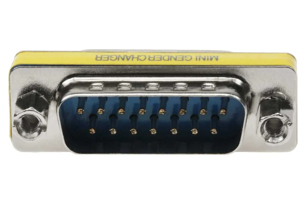
| Core Structure | Mainly includes the D-shaped metal shell, pins/terminals (arranged in parallel rows), and an insulating plastic body. |
| Common Types | Primarily classified by the number of pins, such as DE-9 (9 pins, commonly used for serial ports), DA-15 (15 pins, commonly used for VGA interfaces), and DB-25 (25 pins, commonly used for parallel ports or audio). A high-density (HD) model is also available, housing more pins within the standard housing size. |
| Key Parameters – Pin Pitch | – Approximately 2.41mm (radial x axial) for standard models, approximately 2.0mm or less for high-density models. – Operating Temperature: Typically -55℃ to 125℃. – Rated Voltage: Commonly 300V. |
| Core Advantages | – Rugged and Durable: The metal housing provides excellent mechanical protection and electromagnetic shielding. – Reliable Connection: Screw-fastening design prevents accidental dislodgement. –Standardized: Clear pin definitions and strong compatibility. |
| Main Limitations | – Larger Size: Not suitable for the trend towards thinner and lighter devices. – No Hot-Swapping Support: Most models require power-off connection; otherwise, the device may be damaged. – Limited Transmission Rate: Not designed for modern high-speed data (such as HDMI, USB 3.0+, etc.). |
| Typical Applications | – Video Transmission: The VGA interface is one of the most well-known applications of D-Sub. – Industry and Control: Industrial automation control systems, measuring equipment, etc. – Professional Audio: Uses models such as DB-25 for multi-channel analog audio signal transmission. – Network Device Management: Used for configuration of console ports on routers and switches. |
1. From Selection to Soldering
Understanding the basics of D-Sub connectors is crucial for correctly selecting and using them in actual projects.
Type Selection is the First Step
Select a connector with the appropriate pin count based on the signal type and quantity. If space is limited, consider high-density (HD) connectors. For applications with special environmental requirements (such as outdoor, dusty, or humid environments), choose a ruggedized model with a waterproof seal or special coating.
Pay Attention to Pin Definitions
Pin definitions may differ for different applications. Always consult the device manual or relevant standards (such as RS-232, VGA) to ensure correct wiring.
Soldering and Assembly Points
The soldering and assembly quality of D-Sub connectors directly affects connection reliability.
◦ Check Pins: Always double-check pin definitions and wiring sequence before soldering.
◦ Use appropriate tools: Use a temperature-controlled soldering iron and avoid prolonged high-temperature soldering to prevent damage to connectors or circuit boards.
◦ Safety precautions: Soldering should be performed in a well-ventilated area to avoid inhaling harmful fumes.
◦ Ensure shielding connection: The shielding layer of the D-shaped metal casing should be properly grounded to achieve optimal electromagnetic shielding.
Important Precautions
◦ Avoid hot-swapping: Unless explicitly supported by the device, plugging and unplugging should be done with the device powered off to prevent surge current damage to the interface.
◦ Non-high-power applications: D-Sub is primarily designed for signal transmission and low power levels and should not be used for high-current power transmission.
2. Development, Limitations, and Future
Although D-Sub is a mature technology, understanding its development history and current positioning helps us to view and use it more rationally.
Technological Evolution
Since its inception, the D-Sub connector has undergone continuous evolution in structure and manufacturing processes, roughly going through three generations:
◦ First Generation: Primarily designed to meet military and aerospace needs, it featured a complex structure and high cost.
◦ Second Generation: With the development of the electronics industry, especially the IT sector, improvements in manufacturing processes (such as terminal stamping) significantly reduced costs and increased efficiency, making it the most widely used generation.
◦ Third Generation: The structure was further simplified, resulting in lower costs, to adapt to the more cost-sensitive mass production of consumer electronics.
Current Applications and Limitations
In many traditionally advantageous areas, D-Sub maintains its strong position due to its robustness, reliability, and cost-effectiveness. However, its relatively large physical size contradicts the trend towards thinner and smaller modern electronic devices.
Regarding transmission speed, although high-density improved versions offer enhanced performance, they still struggle to meet the high-speed transmission demands of high-definition video and massive data volumes.
Future Outlook
In the future, D-Sub connectors are expected to continue playing a vital role in areas emphasizing connection robustness, shielding, and cost control, such as industrial control, specialized equipment, and specific communication infrastructure.
3. Summary
The D-Sub connector, a significant milestone in the history of electronic interconnect technology, cleverly balances robustness, reliability, and manufacturing cost. Hopefully, this introduction has helped you gain a more comprehensive understanding of this classic connector.
If you have specific application scenarios you’d like to explore further, or encounter specific problems during the selection process, I’d be happy to continue the discussion.


